Network Analysis 101: The Basic Flow of Data
Articles and Tips: article
01 Jul 1999
Editor's Note: This article is adapted from Introduction to Network Analysis by Laura Chappell. This book is available in both electronic and hard copy form at http://www.podbooks.com.
When I teach classes on protocol and communications analysis, I often find that the audience is missing one fundamental piece of knowledge--a basic understanding of how data flows through a network. For example, how does a packet get from your workstation to the server on another network? How do the interconnecting devices (such as routers, switches, and hubs) affect the path that the packet takes? How do these devices change the content of the packet? Does the packet travel across any networks unnecessarily?
This article explains how interconnecting devices such as hubs, switches, and routers affect the flow of data on a network. Specifically, this articles explains how each device forwards packets and whether or not it changes packets before forwarding them.
This article is a must read for anyone who works on networks. This article doesn't take long to read, so find a nice spot where no one will bother you for 30 minutes.
THE *#&$!? OSI MODEL REVISITED
No matter how much you try, you really can't avoid the Open Systems Interconnection (OSI) model. Don't worry; this article doesn't focus on the entire OSI model--only on the layers that deal with the flow of data on an internetwork.
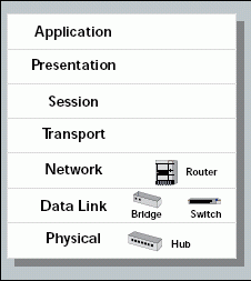
Figure 1 shows the OSI model and the interconnecting devices that work at the first three layers of the model. The following sections explain how these interconnecting devices forward data on a network.
Figure 1: The Open Systems Interconnection (OSI) model and the interconnecting devices
HUB COMMUNICATIONS (LAYER ONE DEVICES)
Hubs, simple multistation access units, and repeaters are the most basic forwarding devices. These devices aren't very intelligent. In fact, they don't know what a packet is; they see only 1s and 0s. Essentially, these devices forward bits from one port to another. For example, a hub receives a 1 bit in one port and copies this 1 bit to all other ports.
Of course, handling packets in this way can create problems if a device sends a broadcast storm. In this case, the broadcast storm affects all of the devices that are connected to the hub. A switch that offers broadcast throttling capabilities or a router may help you better control network traffic. These more advanced products work at the second layer in the OSI mode.
BASIC SWITCH COMMUNICATIONS (LAYER TWO DEVICES)
Bridges usually connect two linear network segments (with one port for each segment). Switches, on the other hand, can connect devices together (with one port for each device). Because most bridges have been replaced by switches, this section focuses on switches.
Switches forward packets based on the destination media access control (MAC) address. Switches learn where devices are located when the devices initially communicate on a network. Switches then put this address information in a table. (See Figure 2.)
Figure 2: Switches forward packets based on the device?s MAC address.
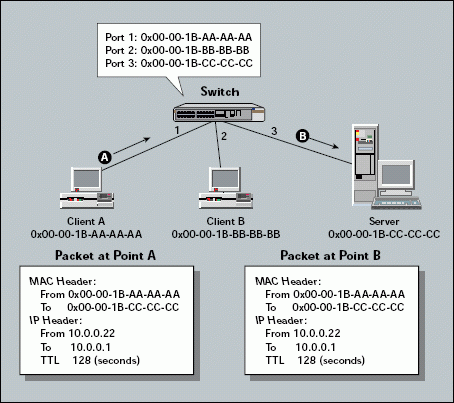
When forwarding a packet, switches do not change the packet's contents (such as the network address or the MAC address). In a basic switched environment, all the devices are on the same network.
Like hubs, switches forward all broadcast packets and multicast packets to all ports. After all, these packets are addressed to a group or set of devices.
Switches also forward packets that are addressed to unknown MAC addresses to all active ports. If a MAC address is unknown, switches assume that they have not yet learned about that MAC address. When the intended recipient replies to the packet, switches learn where the MAC address is located.
Switches typically forward packets quickly because they do not make the more complex forwarding decisions that routers make. Although switches are fast, they have do have some inherent disadvantages. For example, consider how a switch would handle the following:
Part of a network is Token Ring, and the other part of the network is Ethernet.
All devices are communicating with one host or port.
A broadcast storm occurs.
A device sends a fragment.
A switched network contains a loop.
Network traffic must be separated into groupings.
A station sends packets to an invalid address.
Unfortunately, these issues can create problems for basic switches. If you must address one of these issues on your company's network, you must purchase a switch with advanced features, such as the following:
Translational switching
Fat pipes
Broadcast throttling
Fragment-free switching
Spanning tree protocol for loop resolution
Virtual LANs (VLANs)
These features change the basic flow of data in a switched network, as the following sections explain.
Translational Switching
Translational switches can switch between various media access types. For example, if part of a network is Token Ring and the other part is Ethernet, you can use a translational switch to connect the two network segments. Unlike basic switches, translational switches change the contents of a packet: When forwarding packets between two network segments, translational switches convert one type of MAC header to another type of MAC header.
Although this type of switch sounds like a great solution, you may encounter some problems implementing it. For example, not all media access types use the same bit-ordering. If you use a translational switch, packets can become jumbled.
I recommend you use a router to connect different media access types. However, if you decide to use a translational switch, carefully read the manufacturer's directions and configuration books before you implement the switch.
Fat Pipes
What if all devices are communicating with one host or port? If the network data flows in a one-to-many design, you can replace all of the hubs on the network with switches, and network performance will not improve.
For example, suppose a network includes 15 clients and one NetWare server. All of the clients communicate with the server--that's the nature of NetWare's client-server communication system. If you install an eight-port 10 Mbit/s switch, all traffic is sent to and from one 10 Mbit/s port. The network has a single point of congestion when seven devices try to communicate with the server simultaneously. In essence, approximately 70 Mbit/s are being sent to the server's 10 Mbit/s port. The switch's buffering system must hold the packets until bandwidth is available on the server's port.
The term fat pipe is used to define a high-bandwidth port. You typically use fat pipes to connect high-demand devices, such as servers, or high-demand interconnecting devices, such as switches and routers. Even one high-bandwidth port can be a network lifesaver.
For example, you can use a switch with a fat pipe to solve the congestion problem on the hypothetical network mentioned in the "Translational Switching" section. If you connect the server to the 100 Mbit/s port, network performance will improve significantly.
Broadcast Throttling
What if a broadcast storm occurs? A broadcast storm in a switched environment can cause network death--or at least inflict some nasty wounds. For example, suppose a device experiences a failure that causes a broadcast storm of 1,000 broadcast packets per second. How does this broadcast storm affect a network? All devices--regardless of supported protocols--receive and examine broadcast packets. (Of course, if a device examines the packet and determines it is destined for an unsupported protocol, the device may then discard the packet.)
Broadcast throttling enables you to reduce broadcasts to an "acceptable level." You can filter out broadcasts in excess of a specific level. For example, you can set the broadcast throttle level at 100 broadcast packets/second. If a station sends a broadcast storm consisting of 1,000 broadcast packets/second, the switch will forward only the first 100 packets and discard the other broadcast packets. (For more information about managing broadcast traffic, see "Categorize Your Broadcast Traffic" in the podbook Introduction to Network Analysis at http://www.podbooks.com.)
Fragment-Free Switching
How do switches handle fragments? A fragment is a packet that is less than 64 bytes and has an invalid Frame Check Sequence (FCS) value. A fragment is a corrupted packet. If the corruption occurs in the beginning of the packet (which is most often the case), the destination address field becomes garbled. Remember that switches forward packets that have unknown MAC addresses to all active ports. As a result, some switches may forward fragments.
Fragment-free switches buffer and examine the first 64 bytes of a packet (fragments are less than 64 bytes long). These switches discard packets that are less than 64 bytes, ensuring that fragments are not propagated through a network.
Spanning Tree Protocol for Loop Resolution
What if a switched network includes a loop? For example, the network shown in in Figure 3 includes a loop between switches 1, 2, 4, 5, and 3 (following the path of the loop). Network designers may intentionally design loops on a network to provide backup paths.
Figure 3: The spanning tree protocol blocks redundant ports to resolve loops.
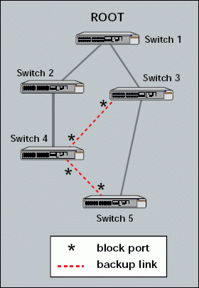
When a device that is connected to switch 5 sends a broadcast packet, where does switch 5 send this packet? Switch 5 forwards the broadcast packet to all active ports, including the ports that connect to switch 3 and switch 4. These switches, in turn, forward this broadcast packet to all their active ports, including the ports that connect to other switches and all other devices on the internetwork.
The spanning tree protocol enables switches to resolve loops. Using this protocol, switches can discover each other and identify ports that should be blocked. In Figure 3, for example, the ports that connect switch 3 to switch 4 and the ports that connect switch 4 to switch 5 are blocked. By blocking ports, switches can establish a single path through the network, thereby resolving loops. (For more information about the spanning tree protocol, see Interconnections: Bridges and Routers, a book written by Radia Perlman and published by Addison-Wesley.)
Virtual LANs (VLANs)
How can a switch separate traffic into groupings? Essentially, switch VLAN technology enables you to "color" the traffic on a network and keep specific traffic (such as broadcast packets) localized to one group, or color. In Figure 4, for example, the network has been logically divided into two networks. In this case, the VLAN1 traffic flows only among VLAN1 devices, and VLAN2 traffic flows only among VLAN2 devices.
Figure 4: One physical network is broken up into two logical networks with VLAN1 and VLAN2.
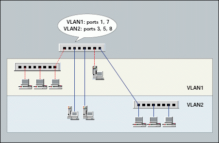
VLANs can be created manually or automatically. If you manually create a VLAN, you set up the membership based on MAC addresses or port numbers. If a VLAN is created automatically, membership can be based on the following:
The protocol (such as an IP VLAN, IPX VLAN, and AppleTalk VLAN)
IP multicast grouping (using a protocol such as Internet Group Messaging Protocol, for example)
If you analyze traffic on a network that includes VLANs, you will see added traffic as the switches communicate VLAN membership information amongst themselves.
VLANs are considered unique networks, and you must always use a router to connect two networks. Therefore, if you want to route packets between two VLANS, you must use a router. It does not matter that the VLANs are virtual; they are still treated as separate LANs.
BASIC ROUTER COMMUNICATIONS (LAYER THREE DEVICES)
Whereas switches can only examine and forward packets based on the contents of the MAC header, routers can look further into the packet to discover the network for which a packet is destined. Routers make forwarding decisions based on the packet's network-layer header (such as an IPX header or IP header). These network-layer headers contain source and destination network addresses.
Local devices address packets to the router's MAC address in the MAC header. After receiving the packets, the router must perform the following steps:
1. Check the incoming packet for corruption, and remove the MAC header . The router checks the packet for MAC-layer errors. The router then strips off the MAC header and examines the network-layer header to determine what to do with the packet.
2. Examine the age of the packet. The router must ensure that the packet has not come too far to be forwarded. For example, IPX headers contain a hop count. By default, 15 hops is the maximum number of hops (or routers) that a packet can cross. If a packet has a hop count of 15, the router discards the packet.
IP headers contain a Time to Live (TTL) value. Unlike the IPX hop count, which increments as the packet is forwarded through each router, the IP TTL value decrements as the IP packet is forwarded through each router. If an IP packet has a TTL value of 1, the router discards the packet. A router cannot decrement the TTL value to 1 and then forward the packet.
3. Determine the route to the destination. Routers maintain a routing table that lists available networks, the direction to the desired network (the outgoing interface number), and the distance to those networks. After determining which direction to forward the packet, the router must build a new header. (If you want to read the IP routing tables on a Windows 95/98 workstation, type ROUTE PRINT in the DOS box.)
4. Build the new MAC header and forward the packet. Finally, the router builds a new MAC header for the packet. The MAC header includes the router's MAC address and the final destination's MAC address or the MAC address of the next router in the path.
Figure 5 shows the contents of a packet before and after it has been forwarded by a router. Figure 5 also shows the contents of the router's routing tables.
Figure 5: Routers forward packets based on the network address.
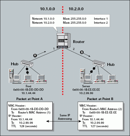
You should try capturing the packets on each side of a router on your company's network. You will be able to see the change in the hop count or TTL value and the new MAC header. When you analyze a communication, you should examine the network layer to determine the actual source and destination of the packet.
What special feats can routers perform that switches cannot? Because routers operate at layer three of the OSI model, they support forwarding based on network addresses (as opposed to forwarding based on MAC addresses or VLAN designations). Routers can also forward packets based on the best known path (especially in the case of link state routers). In addition, routers can provide detailed filters based on the source and destination network address, as well as the source and destination process (as defined in the port number field in the network header).
ROUTERS VERSUS SWITCHES
How do you decide if you should purchase a switch or a router? The following section lists the main differences between the two devices. However, switch and router capabilities vary widely. To find out what capabilities a particular product offers, you should contact the vendor:
Some switches may forward packets faster than a router forwards packets.
You do not need multiple network addresses with a switch (if network addresses are precious).
A switched network has one broadcast/multicast domain.
Routers do not broadcast packets. (Some routers allow you to enable broadcast forwarding, but don't do it!)
Some routers offer sophisticated filtering capabilities.
Routers enable you to use two network addresses (if node addresses are limited).
Some routers can act as a firewall.
Some routers can prioritize traffic.
The following technologies enable routers to perform specialized functions to improve information flow and establish a "first defense" against network intruders:
Traffic filtering and firewalling
Traffic prioritization
Traffic grouping
Variety of routing and routed protocols supported
Traffic Filtering and Firewalling
Sophisticated routers can act as traffic filters--only forwarding a specific type of packet (such as FTP packets, packets from device 10.0.3.2, or IPX traffic). You can use this type of filtering to improve the flow of traffic on specific links or to set up security blocks at key checkpoints. For example, if you want to limit web surfing on your company's network, you can create a simple filter that does not forward any packets addressed to port 80, the HTTP port. (For a complete list of UDP and TCP ports, visit the References section at http://www.netanalysis.org.)
Prioritizing Traffic
Some routers offer traffic-prioritization capabilities. These routers can prioritize traffic based on the time-critical nature of an application or on an application's traffic volume. For example, applications that are time-sensitive are ensured a higher priority to reduce queuing delays. Lower volume applications (such as e-mail) may also be given higher priority so they are not overwhelmed by the big-bandwidth applications (such as file transfer). (For more information about the traffic-prioritization capabilities routers offer, see "Traffic Problems? Making Way for Important Network Packets.")
Grouping Traffic
Grouping traffic is one of my favorite characteristics of IP routers. Devices that want to "join" a particular membership (such as a Service Location Protocol [SLP] client group) can send an Internet Group Messaging Protocol (IGMP) packet. A router tracks the memberships announced and forwards each group's traffic only to ports that are active members of that group. Devices can dynamically join and quit groups by sending new IGMP messages. (To view a sample LANalyzer for NetWare trace that shows IGMP packets, visit the Trace Files section at http://www.netanalysis.org, and download the NetWare 5 connection sequence trace.)
Routed Protocols and Routing Protocols
Routed networks require a bit more sophistication and maintenance than switched networks. For example, on a routed network, you must also pay more attention to the protocols supported.
Two distinct types of protocols determine what a router can do: the routed protocol (which routers use to make forwarding decisions) and the routing protocol (which routers use to distribute route information).
Routed protocols, such as IPX and IP, place headers in a packet to provide the information devices need to forward the packet in the appropriate direction or to discard the packet due to age or corruption. These headers include both source and destination network addresses, as well as some sort of "age" delimiter that indicates how many routers the packet has crossed (hops) or how much further the packet can go (time to live).
IPX and IP Routing Information Protocol (RIP), NetWare Link Services Protocol (NLSP), and Open Shortest Path First (OSPF) are routing protocols. Routers use these protocols to exchange information about routes that are available and routes that become unavailable.
Two types of routing protocols are commonly used:
* Distance Vector Routing Protocols. With distance vector routing protocols, routers exchange simple information about the distance to a network (usually in hops and ticks). Only a single path is used, even if multiple equal-cost paths exist. Routers that use distance vector routing protocols usually choose the path they learn first and ignore other possible equal-cost paths. These routers often exchange distance vector routing information via broadcast packets (ugly).
* Link State Routing Protocols. With link state routing protocols, routers exchange more detailed information about network links and use this information to build a "map" of the network. Link state routing protocols provide a much more complete picture of available paths and costs. In addition, link state routing protocols support multiple paths (for load balancing).
When analyzing network traffic, you should pay particular attention to the routing protocols. What routing protocols are used? How frequently are routing information packets sent? Are the routing information packets sent to the broadcast address (bad) or a multicast address (good)?
EXCEPTIONS TO THE RULES
Both routers and switches change the flow of data through a network. To determine how the switches and routers on your company's network change the flow of data, you must know the exact capabilities these switches and routers provide.
In fact, today's switches and routers are melding together to create what is called layer-three switches or switching routers. These devices typically switch whenever possible (if an entry exists in the MAC address table) and route whenever necessary (if no MAC address exists in the table and the packet is addressed to another network).
Understanding the flow of data is key to performing network analysis. You must know how to interpret the contents of a packet to understand where the packet came from, how far it might have come, and where it is going.
Laura Chappell, a respected author and speaker, is the senior protocol analyst for Network Analysis Institute. You can reach Laura at lchappell@netanalysis.org.
* Originally published in Novell Connection Magazine
Disclaimer
The origin of this information may be internal or external to Novell. While Novell makes all reasonable efforts to verify this information, Novell does not make explicit or implied claims to its validity.