NetWare for SAA 2.0: An Overview of Novell's Next Generation SNA Connectivity Product
Articles and Tips: article
Senior Software Engineer
Host Connectivity Division
01 Mar 1995
This AppNote provides an overview of NetWare for SAA (NWSAA) version 2.0, Novell's latest solution for integrating NetWare LANs into the corporate SNA environment. It starts with brief tutorials on SNA networking and SNA gateways. This AppNote then presents a conceptual overview of the NWSAA configuration process, along with several sample configuration scenarios. Finally, for those interested in developing host-access applications, the AppNote provides a summary of Application Programming Interfaces (APIs) available for NWSAA 2.0.
- Introduction
- The ABCs of SNA
- The SNA Gateway
- NWSAA Configuration Concepts
- PU Profiles
- Configuration Example: Creating Multiple PUs
- Demystifying the PU Profile
- Introduction to NWSAA 2.0 APIs
- Additional Features
- Summary
Introduction
Many of the large enterprise networks that exist today have been built around IBM's System Network Architecture, or SNA. With the evolution of the NetWare network operating system, corporations have been driven to provide their network users with the resources that both SNA and LANs have to offer by integrating NetWare servers into legacy SNA networks. An SNA gateway provides the means of interconnection between LANs and IBM hosts.
This AppNote provides an overview of NetWare for SAA (NWSAA) version 2.0, Novell's latest solution for integrating NetWare LANs into the corporate SNA environment. To provide a better understanding of how NWSAA 2.0 fits into the LAN environment, the AppNote includes brief tutorials on SNA networking and SNA gateways. It then presents a conceptual overview of the NWSAA configuration process, along with several sample configuration scenarios. Finally, for those interested in developing host-access applications, the AppNote provides a summary of Application Programming Interfaces (APIs) available for NWSAA 2.0.
New Product Features
NetWare for SAA has been available for a number of years as a 1.x version of the product, the most current release being NWSAA 1.3b. Recently, the next generation of the product, NWSAA 2.0, has been announced. The following is a list of some of the new features that are incorporated into the latest release:
Multiple PU emulation with the ability to support up to 2000 sessions
Support for SNA Low Entry Networking (LEN) nodes with dependent and independent LUs
Expanded support for AS/400 connections
Load Balancing
Hot Standby
TN3270
Enhanced network management capabilities
New Windows-based configuration utility
New APIs for DOS, Windows and OS/2
LU x / LU A support
New support for CPI-C transaction programs
Compatible with NetWare 3.12 and NetWare 4.10
Compatible with Novell's NetWare Directory Services
Some of these features are discussed in the sections that follow.
The ABCs of SNA
To understand the networking capabilities of NetWare for SAA and how it is used in a LAN, a brief discussion of Systems Network Architecture is in order.
SNA was the first widely-accepted means of interconnecting computers, conceived at a time when networking technology was still in its infancy. SNA has its origins in the world of corporate business computing - an environment where networks are generally hierarchical, and access to network resources is often tightly controlled and prioritized for specific applications. SNA's roots account for the differences between it and other networking architectures, such as TCP/IP which is primarily a product of the academic environment.
SNA has evolved to meet the needs of more modern peer-to-peer networks. It can now be divided into old and new architectures, as described in the following section.
SNA Nodes (Physical Units)
Nodes in an SNA network play well-defined roles according to their Physical Unit or PU type. Four common PU types are defined:
PU Type 5
PU Type 4
PU Type 2
PU Type 2.1
PU Types 5, 4, and 2 essentially comprise the old (hierarchical) SNA, whereas PU type 2.1 defines the new (peer-to-peer) SNA. Every node in an SNA network assumes the role of one of these PU types.
Figure 1 illustrates a generic SNA network with the various PU (node) types and the components that implement them. This is but one of many possible SNA network configurations.
In the diagram, a 3270 display device is attached to a 3174 terminal controller. A NetWare server with NWSAA is used as a gateway for workstations that are attached via both Token Ring and Ethernet LANs. A 37XX Communication Controller provides the Token Ring attachment to an IBM host. A configuration such as this is representative of a hierarchical SNA network.
Figure 1: Major components of an SNA network.
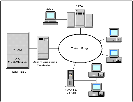
PU Type 5. In the traditional SNA network, PU Type 5 nodes are responsible for session initiation and management. Mainframes running IBM's Virtual Telecommunications Access Method (VTAM) function as PU type 5 nodes, as shown in Figure 1. VTAM serves as the heart of a hierarchical SNA network, monitoring network resources and setting up or tearing down sessions between pairs of logical units (defined below). In order to maintain this degree of control, VTAM must be aware of the network configuration. Hence, tables (called VTAMLSTs) are built on the host which describe to VTAM the characteristics of each network node in its domain. A multi-host SNA network can have multiple VTAMs, with each owning its own set of network resources.
PU Type 4. PU Type 4 nodes can be best described as routers, serving to deliver data to remote locations or internetworking disjoint SNA networks. IBM has implemented PU 4 functionality in its Communication Controller (37XX) products. A communication controller runs software called the Network Control Program (NCP) which performs the function of directing data across different segments of an SNA network (called subareas) or to devices in its own network subarea. Like VTAM, NCP also requires configuration tables which define the paths for data to flow to other SNA subareas.
PU Type 2. The most common SNA node type is the PU Type 2. In older SNA networks, this node type is typically implemented by a terminal controller, such as an IBM 3174; in newer networks, it is implemented by workstations or gateways . A PU Type 2 node serves as the end-point of an SNA network and provides access to "users" of the network - the Logical Units (LUs).
Logical Units
Logical Units provide entry points to an SNA network and establish sessions with other LUs so that work can be accomplished. The concept of a LU is somewhat abstract because it can be represented by a number of different things. Basically, an LU is an entity that provides some kind of services that allow an "end-user" to access network resources. Workstations, printers, and application programs are examples of end-users that employ the services provided by LUs - although each requires a very different means of network access.
Just as there are different PU types, there are also different LU types which are distinguished by the kinds of services they provide. The common LU types are:
LU 1
LU 2
LU 3
LU 6.2
An LU 2, for example, provides services that are used by a display device, such a 3270 terminal; an LU 6.2 provides services in the form of an API which is used by a software applications.
LUs residing on a PU Type 2 all have one thing in common: they function as hierarchical entities and cannot negotiate sessions with other LUs without the intervention of a PU Type 5 node - that is, a mainframe running VTAM.
Peer-to-Peer Node Types
To accommodate peer-to-peer networking environments, IBM introduced the PU Type 2.1 and the LU Type 6.2.
There are actually three types of PU 2.1 nodes, but the differences between them is beyond the scope of this article. NWSAA 2.0 emulates the type of PU 2.1 known as a Low Entry Networking(LEN) node.
LU 6.2 can be thought of as something akin to UNIX named pipes, or TCP sockets. It is a framework for developing applications that perform distributed processing with other applications across a computer network. APPC (Advanced Peer-to-Peer Communication) is an acronym for LU 6.2. Users can develop APPC transaction programs which make use of the LU 6.2 API to communicate with other transaction programs residing on other platforms.
An LU 6.2 residing on a PU 2.1 is no longer dependent on VTAM for session negotiation and control. Hence the name independent LU is frequently used to describe the new SNA node/LU type.
The power of NWSAA 2.0 lies in its ability to emulate more than one PU. A NetWare server with NWSAA can be configured as multiple PU Type 2s, multiple PU Type 2.1s, or any combination of the two.
The SNA Gateway
NWSAA 2.0 allows a NetWare server to function as a gateway between an SNA network and a NetWare LAN. An SNA gateway is essentially a protocol stack whose function is to translate data into the appropriate format as it transverses NetWare and SNA networks. The gateway thus allows a user at a workstation to transparently access applications on an IBM mainframe, AS/400, or any other type of SNA-based node.
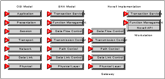
The SNA protocol stack looks somewhat like the layers in the OSI Reference Model. The design of NWSAA 2.0 has split the layers of the SNA protocol stack between the server and the workstation, as shown in Figure 2.
Figure 2: The architecture of NWSAA 2.0 splits the SNA protocol stack layers between the server and the workstation.
Types of SNA Gateways
Traditionally, SNA gateways have emulated a single PU type and fall into one of three categories:
Controller gateways
Pass-through gateways
PU concentrator gateways
Each type of gateway offers pros and cons in terms of the functionality it provides. NWSAA 2.0 allows a NetWare server to function as multiple gateways. By configuring NWSAA to emulate more than one PU, a server can act as a controller gateway, a concentrator gateway, or any combination of the two.
The sections that follow provide an overview of the various types of SNA gateways and the theory of operation of each. This information is useful in understanding the design of NWSAA 2.0 and the various ways in which it can be deployed in a LAN.
The SNA Controller Gateway. The controller gateway is the most common of the SNA gateways. This gateway appears as a PU Type 2 to a host and emulates an IBM 3174 Terminal Controller. Figure 3 shows a typical network configuration using a controller gateway.
Figure 3: The SNA controller gateway.
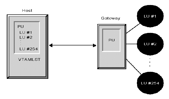
The VTAMLST shown in the diagram is a configuration table that resides on the host and defines the characteristics of the gateway to VTAM. VTAMLSTs are required for every node on the network that will access the respective host. LANs attached to this type of gateway can be Ethernet or Token Ring.
Since the controller gateway emulates a PU Type 2, it also inherits the limitations of this node type, such as a 254 LU (session) limit, which is often not adequate for today's large SNA networks. NWSAA 2.0 has overcome the limitation by allowing a single server to be configured as multiple controller gateways (that is, multiple PU Type 2s), providing for up to 2000 sessions. Thus, with NWSAA, a server configured as a controller gateway allows more users SNA access than many of the similar gateway products available from other vendors which can emulate only a single PU.
The biggest disadvantage of the controller gateways is the lack of interoperability between gateway and workstation. Controller gateways from different vendors frequently vary in their implementation of the SNA protocol stack. Some vendors put the stack entirely on the server, while others distribute the different layers between the server and the workstation. Thus, a workstation which uses the controller gateway must be running software that is compatible with the specific vendor's gateway in order to interoperate.
Early versions of NWSAA overcame this limitation by publishing an open interface, called the QEL/MU Specification, that allowed vendors of SNA workstation products to tailor their software to use NWSAA controller gateways. QELs (Queue Elements) and MUs (Message Units) describe the format of messages that are passed between NWSAA and clients which use the services of the protocol stack. The QEL/MU interface enables 3270 emulators from companies such as Wall Data, Attachmate, and so on to be used in conjunction with an NWSAA server.
The Pass-through Gateway. The pass-through gateway uses a different approach in its implementation of the SNA protocol stack. The pass-through gateway serves as a sort of network funnel to pass SNA data from other PUs to/from a host. Thus, this gateway works like a multiplexor, directing data from multiple sources on a LAN to a single destination. Since data from downstream PUs is merely passed through the gateway unchanged, each LAN workstation must provide the full PU/LU services required by an SNA node that is directly host-attached. Thus, to the host, each workstation appears as a unique PU with attached LUs. IBM has chosen the pass-through approach for its high-end gateway products, such as the 3745 Communication Controller and the 3174.
The pass-through gateway has two main advantages. First, since it is transparent to the network, workstations that access the gateway can use an SNA protocol stack developed by any vendor, as opposed to one that is tied specifically to the gateway (as in the case of the controller gateway). Secondly, since the host sees each workstation using the pass-through gateway as a separate PU (each capable of supporting its own LUs), it eliminates the 254 LU limit that is characteristic of the controller gateway.
Another advantage of the pass-through gateway is that it allows simplifies network maintenance-less configuration is required as new nodes are added to the network
The downside of the pass-through gateway is that, since workstations appear as individual PUs to the host, each one incurs a substantial amount of overhead in terms of the buffers and control blocks that VTAM must allocate to support it. Thus, the pass-through gateway trades easier maintenance and higher capacity (that is, more LUs) for the expense of network performance.
The PU Concentrator Gateway. The PU concentrator is perhaps the most interesting of the three types of SNA gateways. The architecture for this gateway was first introduced by IBM with the release of OS/2 Extended Edition (now called Extended Services) and has since been employed by other gateway products, notably NWSAA 2.0.
The PU concentrator gateway incorporates the best features of both the controller gateway and the pass-through gateway. It contains a hybrid version of the SNA protocol stack with a "split personality" that has the characteristics of multiple PU types. To a host or communication controller (PU Types 4 and 5, respectively), the PU concentrator appears as a single PU Type 2; to a LAN workstation, the concentrator gateway appears as a PU Type 4 or 5.
Figure 4 shows a block diagram of a concentrator gateway.
Figure 4: The SNA concentrator gateway.
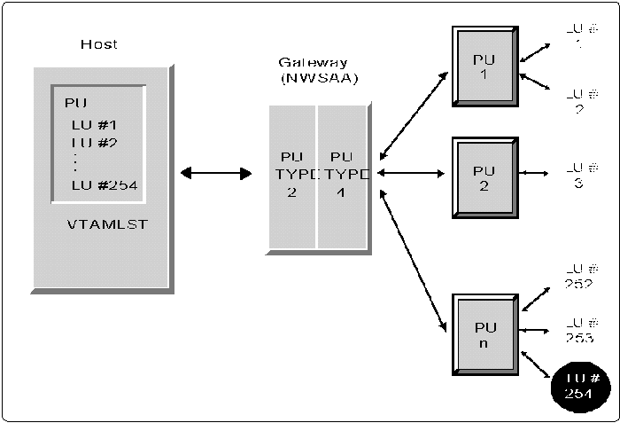
The diagram illustrates how the SNA protocol stack is split to present the appearance of different PU types to opposite sides of the network. The PUs in the diagram are individual 3270 workstations, OS/2 clients, or any other product capable of emulating a PU Type 2.
Workstations that use the concentrator gateway (these are called downstream PUs) must contain a complete SNA PU Type 2 protocol stack, because from their perspective, they are communicating directly with a PU Type 4/5. Thus, the concentrator gateway assumes the role of a pseudo-host and issues the SNA command sequences that would normally be sent by VTAM or NCP to activate each downstream PU. But from the point in time where each downstream PU becomes initialized, the concentrator gateway changes personalities and functions like a pass-through gateway, transparently passing data through to its intended destination.
The advantage of the concentrator gateway is that it combines the low overhead of the controller gateway with the transparency of the pass-through gateway. Since it appears as a single PU to the host, it incurs minimum overhead-that is to say, it requires only a single VTAMLST definition, thus minimizing the use of precious VTAM resources (buffers, control blocks, and so on). Because the concentrator gateway behaves similarly to a pass-through gateway, it is compatible with any vendor's SNA PU 2 emulation product. Thus, companies with investments in emulation products, such as IBM's OS/2 or UNIX 3270 products, can continue using these programs on their LAN workstations while deploying an NWSAA 2.0 NetWare server as a gateway to an SNA host.
As with the controller gateway, an NWSAA 2.0 server configured as a concentrator gateway can be partitioned into multiple PUs, each supporting up to 254 downstream PUs. This configuration expands the capacity of a concentrator gateway beyond the limits of most other vendors' implementations.
NWSAA Configuration Concepts
Now that we have a basic understanding of SNA networks and the various types of SNA gateways, we can turn our attention to concepts that are more specific to configuring NWSAA as an SNA gateway.
A Word About NWSAA Data Links
In addition to whatever LAN attachment is used for a NetWare server, data links to the SNA network are also required for NWSAA gateways. Typically, SDLC or Token Ring is used to connect to either a host computer or to another NWSAA server. In NWSAA, the term "link" is used in an ambiguous manner: a NIC (network interface card) supports one physical link, which in turn can support multiple logical links. Thus, a single Token Ring NIC might support more than one connection (logical link) to a single host, or multiple connections to multiple hosts.
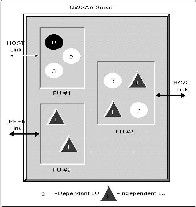
HOST vs. PEER Data Links. NWSAA 2.0 makes a distinction between two types of logical data links: HOST and PEER. Each PU that is configured on the server will use either a HOST or PEER logical link. The type of link is determined by the kind of LUs that reside on the PU: dependent or independent.
An understanding of the differences between HOST and PEER links is necessary to configure an NWSAA server, as the configuration process involves creating either HOST or PEER PU profiles. Thus, it becomes important to know the differences between dependent and independent LUs.
Dependent vs. Independent LUs. Dependent LUs exist under the old SNA and require intervention by a PU 5 (VTAM) to establish sessions with other LUs. In order for a dependent LU to become active (that is, able to communicate on the network), VTAM must issue a series of commands which first activate each PU (called an ACTPU) and then activate each of the LUs (ACTLU) that belong to the PU. By definition, LU Types 1, 2 and 3 are always dependent, while LU 6.2s can be either dependent or independent. In the parlance of NWSAA 2.0, links used by PUs with dependent LUs (that is, LUs that require ACTPU/ACTLU commands) are called HOST links.
Independent LUs, on the other hand, are capable of negotiating sessions without first being activated by VTAM. Under the new SNA, independent LUs reside on a PU 2.1 node which has the capability of providing the necessary services for session initiation with other independent LUs within the SNA network. In NWSAA, links used exclusively by independent LUs are referred to as PEER links, as no ACTPU/ACTLU commands flow on them.
To summarize:
In NWSAA 2.0, a logical link is defined as a HOST link if the associated PU has dependent LUs.
A link is defined as a PEER link if the corresponding PU has solely independent LUs.
It is also possible to have a PU which supports both dependent and independent LUs. Such a PU employs a HOST link, as VTAM activation commands destined for the dependent LUs must still flow across it. The SNA architecture specifies that a PU 2.1 can accommodate a combination of dependent and independent LUs.
Figure 5 illustrates the concept of an NWSAA 2.0 server partitioned into (that is, configured as) multiple PUs of various types: one with dependent LUs only, another with independent LUs only, and a third with a combination of the two. The type of logical link associated with each PU is also shown.
Figure 5: NetWare for SAA data links.
PU Profiles
Configuring NWSAA 2.0 is essentially the process of logically partitioning the server into one or more PU(s) by creating PU Profiles. A PU Profile defines the characteristics of the corresponding PU. Creating a PU Profile typically involves assigning the following parameters, which define a node in an SNA network:
Network ID
Control Point (CP) name
Node ID
The LU types residing on the PU
On an NWSAA 2.0 server, two types of PU Profiles can be configured:
HOST PU Profiles, which create PUs with HOST links.
PEER PU Profiles, which are used for PUs requiring PEER links.
Within NWSAA 2.0, all PUs are essentially created equal - with one exception: the D efault PU.
The Default PU
On an NWSAA 2.0 server there is a single PU 2.1 that is always present by default, even if no other PU profiles are defined. The Default PU differs from PUs created from PU Profiles in that it can use multiple physical network interface cards (NICs) for SNA data links.
Normally, during the course of configuration, it is necessary to map a NIC to each PU Profile that is created. LUs belonging to that profile are constrained to using the logical link(s) associated with the NIC that has been assigned. By contrast, LUs belonging to the Default PU can use any of the logical links (on any NIC) that are available to the server.
The concept of the Default PU is illustrated in Figure 6.
Figure 6: Configuring a NetWare for SAA 2.0 server.
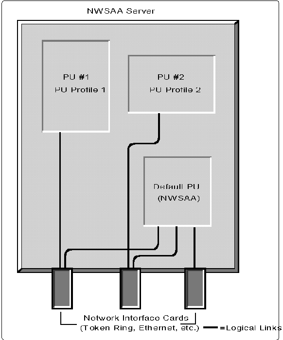
The server in the diagram has been partitioned into three PUs, in part by creating the PU profiles PUPROF1 and PUPROF2. The profile for the Default PU, called NWSAA, is essentially "built-in," but some configuration of this PU profile is also required. The diagram shows how the Default PU can access an SNA network via any of the NICs installed on the server. The remaining PU profiles can use only the logical links assigned to a single adapter - the one specified during configuration.
How the Default PU Is Used
What is the purpose of the Default PU? In NWSAA 2.0, the Default PU is intended to be the PU 2.1 that provides the independent LUs for use by all APPC transaction programs. This is because it supplies all the connectivity resources, including the multi-adapter capability, that a transaction program would generally require. The Default PU provides strictly independent LUs - no dependent LUs can be assigned to it. Since the Default PU can be considered as a sort of general-purpose PU, it is normally not necessary to create other PU 2.1s by defining additional PEER PU profiles. However, there is an exception to this, which is discussed later.The Default PU is also the PU that is automatically assigned when the NWSAA server is configured for AS/400 connectivity.
Configuration Example: Creating Multiple PUs
There are two main steps to configuring an NWSAA 2.0 server. The user first determines the type of link that is required (HOST or PEER), and then proceeds to create either a HOST PU profile or a PEER PU profile with the necessary SNA node parameters, dependent LU definitions, and so on.
The SAACON utility is used to perform actual configuration of an NWSAA 2.0 server. SAACON is invoked by the CSCON utility, which provides the capability of performing configuration of any LAN-attached NWSAA server from a single location. An illustration of the SAACON main menu is shown in Figure 7.
Figure 7: Main menu of the SAACON utility.
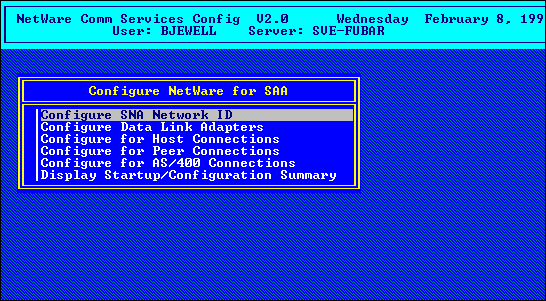
As seen from the panel, SAACON is also used for other administrative tasks, such as creating LU Pools, configuring the Hot Standby feature, or TN3270.
A Sample Network
Figure 8 provides an example of an SNA network that will be used to illustrate a conceptual overview of the NWSAA configuration process.
Figure 8: Sample network for demonstrating the configuration of an NWSAA 2.0 server.
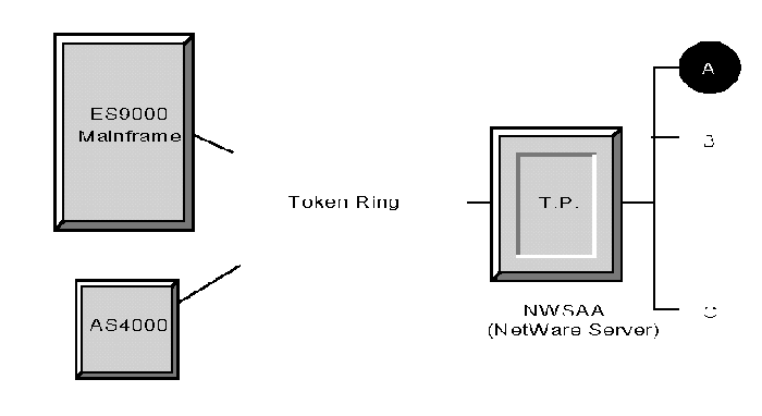
In the diagram, a Token Ring network is used to connect an ES/9000 mainframe, an AS/400, and a NetWare 4.10 server with NWSAA 2.0 installed. An Ethernet network connects workstations on the LAN, which are assumed to be PCs running the NetWare DOS Requester software. The additional requirements for this hypothetical network are as follows:
Workstations A and B will perform 3270 emulation and access applications on the ES/9000
Workstation C requires access to the AS/400
The server will be running an NLM APPC transaction program (shown in the diagram as TP) which communicates with a partner transaction program that resides on the ES/9000.
Under this scenario, NWSAA has been partitioned into three PUs (that is, PU profiles): a HOST PU, a PEER PU, and the Default PU. As previously mentioned, most SNA network topologies would not require the creation of a PEER PU profile; the default PU is used for almost all APPC applications. But a somewhat off-the-wall configuration has been chosen in this example to illustrate the concept of the PEER PU profile, which can be somewhat difficult to understand.
The following sections describe the configuration process for each of the three requirements listed above.
Configuring NWSAA for 3270 Emulation
Figure 9 illustrates the concepts of configuring NWSAA for workstations A and B, which will be doing 3270 emulation. This is perhaps the most traditional use of the gateway.
Figure 9: Configuring workstations A and B for 3270 emulation.
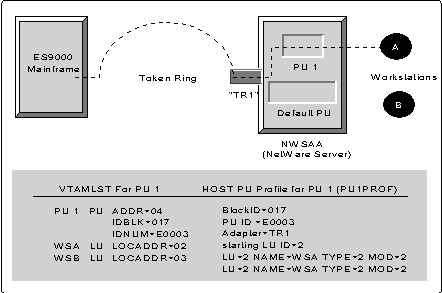
Figure 9 shows a PU, called PU 1, which has been defined for the purpose of 3270 emulation. Since dependent LUs are always used for 3270 emulation, PU 1 has been created by defining a HOST PU Profile, called PU1PROF, whose partial contents are shown at the bottom of the illustration. Two LUs, one for each of the workstations A and B, have been assigned to PU 1. The Token Ring adapter, named TR1, has been mapped to PU 1 in the PU profile.
The default PU is also shown as a reminder that it is always present, even though it is unused in this configuration. Other configuration parameters, including portions of the required host VTAMLST, are also shown in the diagram.
This scenario provides a very generic example of doing 3270 emulation with NWSAA. More complex configurations than the one illustrated are usually required, such as multiple sessions for workstations, or creating LU pools for groups of dependent LUs. Using NWSAA for 3270 emulation always requires that a 3270 emulation package (such as Attachmate or Wall Data products) be installed on each workstation, but this is not shown in the diagram.
One additional aspect of configuring NWSAA for 3270 emulation is the support provided for different kinds of LUs (not to be confused with different types of LUs defined by SNA). When LUs are defined for a HOST PU profile, there are three types to choose from (how an LU is typed determines its accessibility from a NetWare LAN):
Public LUs are available for use by any workstation that connects to an NWSAA server.
Pooled LUs, as the name implies, are assigned to a pool and can be allocated only by workstations that are authorized to use the pool.
Dedicated LUs are LUs that are set aside for use by a specific workstation only.
In some SNA networks, it is desirable for a given LU (or several LUs) to be configured specifically for a certain application - say, for a network administrator who requires higher priority access to network resources than basic users (in SNA, this is referred to as class of service). Dedicated LUs allow for this contingency, as they are assigned for use only by a specific user or workstation.
Configuring an AS/400 Connection
Configuring an NWSAA server for attachment to an AS/400 provides an opportunity to further discuss the application of SNA's APPC (LU 6.2). This is because an AS/400 functions as a PU 2.1 node with data going to/from it transported on APPC sessions between one or more independent LUs. To access an AS/400, a LAN workstation effectively runs an APPC transaction program (called an AS/400 Router) that uses an independent LU allocated on the NWSAA server to engage in a session with a partner LU in the AS/400. Data that is sent or received on behalf of the LAN workstation flows on the session between these two LUs.
AS/400 connectivity also provides an example of how the Default PU is used by NWSAA. When the Configure For AS400 Connections selectionis made in SAACON (see Figure 7), the PU Profile of the Default PU is automatically chosen by the configuration program to be used for the connection. The session capacity provided by the Default PU is usually adequate for most AS/400 installations.
AS/400 configuration consists of three basic steps:
Configuring the Default PU (this is required for every NWSAA server).
Assigning users and sessions (this step is optional).
Defining system information for each AS/400 host to which users will connect.
Figure 10 illustrates the concepts involved with AS/400 connectivity.
Figure 10: Configuring workstation C for an AS/400 connection.
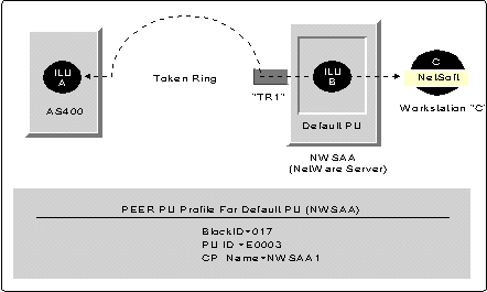
On the NWSAA server, the Default PU is shown with a single independent LU (labeled as ILU B) allocated for use by workstation C; on the AS/400, a corresponding partner LU (ILU A) exists. Data from workstation C flows across the LAN to NWSAA where it transported on the LU 6.2 session between the two independent LUs, ILU A and ILU B. An independent LU is allocated on the NWSAA server for each LAN workstation that connects to the AS/400.
Not shown in Figure 10 are two NetWare Loadable Modules (NLMs) that implement a portion of AS/400 connectivity in NWSAA. These modules are worthy of mention:
PB_NWSAA.NLM provides APPC services for NetWare-based transaction programs (that is, the APPC verbs)
AS400PCS.NLM is an APPC transaction program which serves as the interface between the AS/400 router software running on a workstation and a partner transaction program running on the AS/400.
NWSAA 2.0 includes an AS/400 router product from NetSoft that runs under MS Windows and is installed on each LAN workstation requiring AS/400 connectivity. The NetSoft Router program communicates with AS400PCS.NLM, which allocates a single independent LU on the NWSAA server for each LAN workstation that connects to it. Each AS/400 display session on a workstation uses a single LU 6.2 session between the local (NWSAA) LU and partner (AS/400) LU for transport.
For the sake of simplicity, workstation C was chosen to have only a single session in the sample network described in Figure 8. But since independent LU 6.2s are capable of supporting parallel sessions to the same partner LU, or multiple sessions to different partner LUs, a single workstation can support up to 32 simultaneous display sessions to one or more AS/400(s).
It is worth noting that configuring NWSAA for AS/400 connectivity is a much simpler process than configuring for 3270 emulation, as in the example of workstations A and B above. This is because IBM's AS/400 product is representative of the new generation of peer-to-peer SNA networking. The NWSAA Default PU 2.1, which is used for AS/400 connectivity, is capable of negotiating the required network parameters with the AS/400 (also a PU 2.1) during the XID exchange which occurs during link activation. Thus, the need to define the various connection parameters beforehand, as in the case of PU 2, has been minimized. In NWSAA 2.0 the bulk of the AS/400 configuration process involves the optional setting up of the security features that can be used to limit AS/400 access for workstations on the LAN.
Configuring an APPC Connection
The final requirement for the hypothetical network of Figure 8 is to configure NWSAA to run an APPC NLM transaction program which is to converse with a partner TP on the ES/9000. This example has been chosen to demonstrate the use of a PEER PU Profile. (Note that it would have been equally valid to have used a transaction program running on a LAN workstation instead of as an NLM).
APPC Overview. To fully understand how NWSAA is configured for an LU 6.2 transaction program, a further explanation of APPC is in order.
APPC transaction programs (TPs) are typically found in pairs. There is generally a local TP running on a workstation (or in the server as an NLM). This local TP uses APPC to establish a conversation with a remote TP to perform some kind of work. An APPC transaction program is not limited to a single conversation. It can establish parallel conversations with a partner TP or multiple conversations with different partner TPs.
Figure 11 illustrates the concept of how an APPC transaction program works. Since conversations between TPs occur over LU 6.2 sessions, configuration of an LU and a corresponding PU is required in order actually run the TP. An independent LU has been chosen for the transaction program in our example network.
Figure 11: APPC transaction programs.
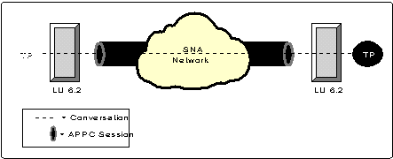
When a transaction program is written, calls are made to APPC verbs to perform the task of initiating conversations and communicating with a partner TP. An analogy to APPC verbs exists with TCP/IP Sockets, another vehicle for developing distributed applications.
There is actually more than one flavor of the APPC verb set. The earliest is the so-called APPC/PC verbs, which are compatible with IBM's first PC-based implementation of APPC. In order to use the APPC/PC verbs, the TP must provide a certain amount of configuration information so that a session can be established with a remote LU, over which a conversation can occur. The earlier release of NWSAA 1.3 supported the APPC/PC verb set; NWSAA 2.0 supports the APPC/PC verb set as well as others which are discussed later in this AppNote.
Setting Up the PEER PU Profile. The purpose of the PEER PU profile is essentially to maintain backward compatibility with TPs that were developed under NWSAA 1.3 and implemented using the APPC/PC verbs. In NWSAA 1.3 (where only a single PU was supported), it was necessary to create a profile for a PU 2.1 and match the configuration information stored in the profile with the configuration information coded in the TP.
In NWSAA 2.0, all transaction programs normally use the services provided by the Default PU. However, the profile defined for this PU often contains configuration parameters which do not match those of an NWSAA 1.3 transaction program. So to allow an NWSAA 1.3 TP to be run on an NWSAA 2.0 server without modifying the program, it is possible to create an additional instance of a PU 2.1 (by defining a PEER PU profile) that effectively emulates an NWSAA 1.3 PU. This is illustrated in Figure 12.
Figure 12: Configuration for APPC.
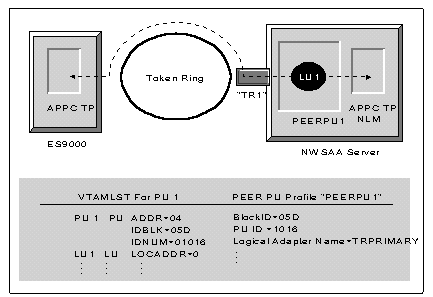
In this configuration, the TP NLM (from Figure 8) requires a conversation with a partner TP on the ES/9000. Since we are assuming that this TP contains some hard-coded configuration parameters which are incompatible with the profile defined for the Default PU, a PEER PU profile (called "PEERPU1") has been created. This essentially provides a PU/LU instance for use by the TP for the conversation with its partner.
Portions of the corresponding PEER PU profile and host VTAMLST are also shown in Figure 12. Note that independent LUs are not explicitly defined either in the PU profile or the VTAMLST. This is because independent LUs negotiate session parameters when they bind (initiate a session) and hence do not require tables of configuration parameters to be created by an administrator, as in the case of LU Type 2 (3270 emulation).
Note: NWSAA 2.0 includes a utility program (which can be run as part of the installation process) that automatically converts old PU 2.1 profiles created for NWSAA 1.3 servers to the newer (NWSAA 2.0) PEER PU profiles.
Demystifying the PU Profile
Understanding what really occurs (from an SNA perspective) when a PU profile is defined, and when to use a PEER profile instead of a HOST profile, can be somewhat confusing. So one final explanation on the subject is offered.
Note: This section is intended primarily for SNA techies and should probably be avoided by the faint-at-heart.
Defining an NWSAA PU profile, regardless of whether it is a HOST or PEER, essentially creates an instance of a PU 2.1 on the NetWare server. In SNA terms, this means that an XID-3 is always sent on behalf of the PU instance during link-level negotiation which occurs at startup. The "personality" of the PU 2.1 created by a profile is determined to a degree by whether the profile is a HOST profile or PEER profile. For HOST profiles, a flag is set in the XID-3 that indicates NWSAA expects an ACTPU to be sent on this link; for PEER profiles, the flag is set to indicate that no ACTPU will be accepted.
Since each profile that is defined creates an instance of a PU 2.1 LEN node, and, by definition, a LEN node can support a combination of dependent and independent LUs, HOST profiles can be used for both LU types (dependent and independent). It is even possible to define a HOST profile with zero dependent LUs for use exclusively by independent LUs. From an SNA network perspective, defining a HOST profile with zero dependent LUs is equivalent to a creating a PU by defining a PEER PU profile, except that an ACTPU command will flow on the link.
The main purpose of the PEER profile is to maintain the "look and feel" of the configuration process as it existed in NWSAA 1.3. Also, from a system standpoint, PEER PU profiles incur less overhead (buffers, streams, and so on) than HOST PU profiles. But technically speaking, defining either type of profile should be thought of as simply creating another LEN node on the NWSAA server. If a PU requires dependent LUs, a HOST profile must be used; otherwise HOST and PEER PU profiles are logically equivalent.
Introduction to NWSAA 2.0 APIs
One of the more significant features of NWSAA 2.0 is the enhanced support of SNA Application Programming Interfaces (APIs). This has become an integral part of NWSAA as customers have migrated toward using the peer-to-peer capabilities of the new SNA. The SNA APIs are used for development of transaction programs that do distributed processing across SNA networks and NetWare LANs.
Figure 13 provides a chart showing the NWSAA 2.0 APIs that are available and the platforms on which they are implemented.
Figure 13: NWSAA 2.0 APIs and available platforms.
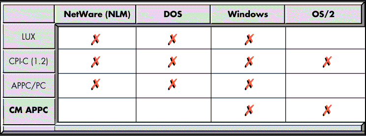
Note: At the time of this writing, not all of these platforms are supported for the APIs listed in the diagram, but these are in the process of being implemented.
The difference between the APIs lies in the level of services that they provide. The lower-level APIs, such as APPC/PC, require a much broader knowledge of SNA to use than do the higher-level APIs, such as CPI-C.
Figure 14 shows the architecture of the NWSAA 2.0 APIs.
Figure 14: The NWSAA 2.0 API model.
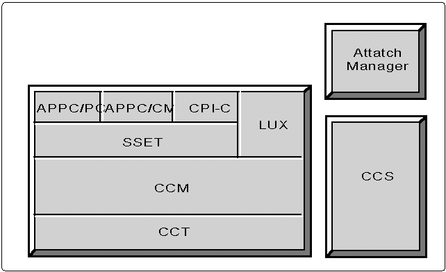
The actual APIs available to users, which will be described later, are represented by the boxes labeled APPC/PC, APPC/CM, CPI-C and LUx. The remaining components SSET, CCM, CCT and CCS provide the "glue" between the APIs and the NWSAA protocol stack . The modular design of the APIs allows for a degree of portability of the components across different O/S platforms. Thus, the components shown in Figure 14 are present in any environment where the APIs are used: DOS, Windows, or NetWare.
The components of NWSAA 2.0 APIs can be described as follows.
SSET Layer. The common APPC APIs (APPC/PC, APPC/CM and CPI-C) share a protocol boundary with the SuperSet (SSET) layer. SSET is responsible for processing Verb Parameter Lists, or VPLs. (VPLs are functionally equivalent to QELs of the previously mentioned QEL/MU interface used by emulator vendors). Thus, the SSET component insulates the APPC API implementations from the intricacies of communicating with the NWSAA protocol stack.
LUx API. Note that, in Figure 14, the LUx API bypasses the SSET layer to go directly to the CCM. This is because the services provided by SSET are designed for APPC API implementations and LUx is a 3270-like API which communicates differently with the NWSAA protocol stack.
CCM and CCT Layers. The Client Connection Manager (CCM) layer serves to route messages over the appropriate path to NWSAA. The lowest layer of the API model, Common Client Transport (CCT) provides services to send and receive messages. This is a platform-specific component of the APIs, since the mechanism used for transport is dependent on the OS: SPX for DOS environments; Transport Layer Interface (TLI ) for Windows environments; and S treams for NetWare NLMs.
CCS API. The remaining component of the APIs, Common Client Services (CCS), is also OS-specific and functions to provide the other components with services that perform file I/O, memory management, and so on. CCS is actually accessible by all the other API components, although this is not apparent from Figure 14.
Attach Manager. One other component of the NWSAA APIs, the Attach Manager, requires some additional explanation. One of the properties of APPC, as defined by the architecture, is the ability of a transaction program on one node to launch a transaction program on another node so that program-to-program communication can occur. Thus, a transaction program running on a DOS workstation, for example, can invoke a partner program residing on a separate platform, such as an ES/9000 or another LAN workstation, and cause it to begin execution.
The Attach Manager, which is patterned after its OS/2 counterpart, provides this capability by communicating to NWSAA the location of transaction programs which it might ultimately have to invoke if requests are received from other APPC transaction programs.
APPC/PC
As previously mentioned, this is the original PC-based implementation of the APPC verbs for use by LU 6.2 transaction programs. The APPC/PC verb set provides a low-level API that consists of verbs that fall into one of three types:
Control
Conversation
Network Management
The APPC/PC verb set is more complicated to use, in that the transaction program must invoke control verbs to perform the task of creating an instance of an LU which can engage in a session with a partner LU. Once this is done, one or more sessions could be established over which the conversation(s) could occur. Thus, the transaction program writer was required to posses an understanding of how SNA sessions work in order to successfully execute the control verbs and create a LU-LU session.
Figure 15 illustrates the verbs of the APPC/PC verb set grouped according to type.
Figure 15: Verbs in the APPC/PC verb set.
|
Control Verbs
|
Conversation Verbs*
|
Network Mgmt. Verbs
|
|
ACTIVATE_DLC |
(MC_)ALLOCATE |
TRANSFER_MS_DATA |
|
ATTACH_LU |
(MC_)CONFIRM |
|
|
ATTACH_PU |
(MC_)CONFIRMED |
|
|
CHANGE_LU |
(MC_)DEALLOCATE |
|
|
CNOS |
(MC_)FLUSH |
|
|
DETACH_LU |
(MC_)GET_TYPE |
|
|
DISPLAY |
(MC_)PREPARE_TO_RECEIVE |
|
|
GET_ALLOCATE |
(MC_)RECEIVE_AND_WAIT |
|
|
MODIFY_LU |
(MC_)RECEIVE_IMMEDIATE |
|
|
TP_ENDED |
(MC_)REQUEST_TO_SEND |
|
|
TP_STARTED |
(MC_)SEND_DATA |
|
|
TP_VALID |
(MC_)SEND_ERROR |
|
|
(MC_)TEST |
*Note: BASIC conversation verbs and MAPPED conversation verbs are identical except that MAPPED verbs are preceded with the "MC_" prefix.
The conversation verbs come in two flavors: Basic and Mapped, which are denoted by the MC_ (mapped conversation) prefix attached to the verb. Although the basic and mapped verbs appear to be identical, basic conversations require the transaction program to build a more complete data record before it can be sent to a partner TP.
The APPC/PC verbs were also supported in NWSAA 1.x, the previous release of the product.
CPI-C
The Common Programming Interface Communications, or CPI-C, API can be thought of as a front end to the APPC verbs. CPI-C is an X/OPEN standard composed of a set of program calls which ultimately invoke APPC verbs. The purpose of CPI-C is to provide a standard API for APPC that is consistent across all platforms and serves to insulate the TP from the intricacies of SNA networking. Thus, distributed processing programs written with CPI-C become easier to develop. Figure 16 illustrates the concepts of the CPI-C API.
Figure 16: CPI-C transaction programs.
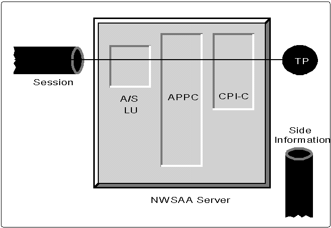
Regardless of the APPC API that a transaction program uses, the SNA fundamentals remain the same: a session between two LUs must exist to serve as the pipe through which a conversation (between two TPs) can flow. CPI-C makes it possible for the mechanics of establishing the session (opening the pipe) to be performed outside of the transaction program.
To accomplish this, NWSAA CPI-C programs use a special type of LU, called an Application Subsystem (A/S) LU for their sessions. In order to further explain CPI-C, it is necessary to diverge for a discussion of an A/S LUs.
Application Subsystem LUs are special LU 6.2s that are created during NWSAA configuration so that they are available for use by transaction programs written with the APPC APIs other than APPC/PC. A/S LUs provide the resources required for a conversation up-front before the TP begins execution. This relieves the TP of the task of executing control verbs. A/S LUs are configured in NWSAA by selecting the Configure APPC Application Subsystem panel in SAACON, shown in Figure 17.
Figure 17: The Configure APPC Application Subsystem menu in SAACON.
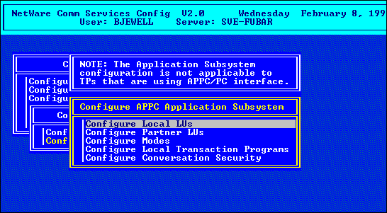
Configuring A/S LUs effectively creates a pool of APPC sessions that are available for use by CPI-C transaction programs to engage in conversations.
Referring back to Figure 16, the CPI-C program is using a session established by an A/S LU as a pipefor a conversation with a partner program somewhere in the network. When A/S LUs are configured as independent LUs, they are always assigned to the Default PU.
An additional component of CPI-C which requires some explanation is the side information file (also shown in Figure 16). When two partner TP programs converse, there is always an initiator of the conversation and a receiver of the conversation. The side information file is created to provide the initiating TP with information about the receiving TP so that an ATTACH (a type of SNA RU) can be built and sent across the network to begin the conversation.
In NWSAA 2.0, the side information file is created by running the APICFG program. There are actually DOS, Windows, and NetWare versions of APICFG; the appropriate one to use is determined by which platform the CPI-C program will execute on.
Note: Between NWSAA 1.3 and NWSAA 2.0, the contents of the side information file was changed. Thus there is a lack of backward compatibility between CPI-C configurations that were created for the earlier release. This is resolved by a conversion utility (included with NWSAA 2.0) that will convert the older style of side information file to the new format.
The concept of Application Subsystem LUs is not native to NWSAA 2.0, but it emulates the design of IBM's OS/2. This allows CPI-C programs written for OS/2 platforms to execute on NWSAA clients.
APPC/CM
APPC/CM is a more recent specification of an LU 6.2 API which is implemented in the IBM Communication Manager (CM), an add-on product for OS/2 systems. Although not available at the time of this writing, the NWSAA APPC/CM API will allow portability of APPC transaction programs between OS/2 and NWSAA environments. The purpose of APPC/CM is similar to that of CPI-C: to make transaction programs easier to develop by eliminating the task of defining LUs and creating sessions from the TP. The APPC/CM API is a lower-level API that requires more APPC knowledge to use than does CPI-C, but places the TP more in control of the network resources.
LUx
The NWSAA LUx API is an offshoot of the SNA LUA API which was originally developed by IBM to provide SNA customers, such as financial institutions, with what might be called a "roll your own" approach to distributed processing across SNA networks. By using LUA, applications can essentially implement their own higher-level protocols, without regard to the standard rules imposed by SNA. This is useful in networks deploying specialized devices, such as automated teller machines, where existing SNA protocols such as 3270 data streams do not adequately meet the requirements of distributed applications. The LUx API is currently in use by financial institutions on some large NetWare LANs, notably Chase Manhatten Bank.
The NWSAA 2.0 LUx API is functionally equivalent to the IBM LUA API, except that LUx verbs are posted using callbacks, rather than OS/2 queues or semaphores (the mechanism used by IBM LUA implementations). This results in LUx being platform independent - hence the name change from LUA to LUx. Applications written for LUA will run with minimal changes using the NWSAA LUx API. Since LUx is essentially a freeform type of SNA API, it can be used to communicate with LU types 0, 1, 2 and 3 (dependent LUs) on a host. The flexibility provided by LUx makes it ideal API for specialized applications in an SNA environment. It is interesting to note that some vendors are using LUx - instead of the QEL/MU interface - to develop 3270 emulation products that are compatible with NWSAA.
Additional Features
NWSAA 2.0 has incorporated some additional features that are designed to address the needs of larger heterogeneous networking environments. For example, TN3270, which is bundled with the NWSAA 2.0 product, allows workstations with TCP/IP protocol stacks to communicate directly with NWSAA servers. Also, the QEL/MU interface has been extended to provide load balancing so that SNA sessions can be evenly distributed across networks that deploy multiple NWSAA servers. These are some of the new features discussed in the sections that follow.
TN3270
As the use of TCP/IP has become common in enterprise networks, the need for access to mainframe-based 3270 applications from TCP/IP hosts has emerged. TN3270, which began as Internet RFC #1041, is an application designed to provide a means whereby users of TCP/IP networks can transparently access mainframe-based 3270 applications via gateways. With TN3270, an SNA host is unaware that the end-user system is a TCP/IP host, rather than an SNA device.
Figure 18 illustrates the principles of TN3270 for NWSAA 2.0.
Figure 18: TN3270.

The workstation runs a TCP/IP protocol stack, such as Novell's LAN Workplace product, along with the TN3270 package. Data flows across a Telnet session between the server and the workstation. The main NWSAA component, NWTN3270, is an NLM which duplicates the functionality of the upper layers of the SNA protocol stack (which would normally reside on the workstation 3270 emulator) and translates data into the QEL/MU format that the NWSAA protocol stack understands. An LU (and a corresponding PU) are configured for NWSAA, just as for any 3270 session.
At the start of a TN3270 session, negotiation occurs between the server Telnet (telnetd) and the workstation Telnet to establish the necessary virtual terminal protocols required by TN3270. When this negotiation is complete, the server Telnet hands off the session to NWTN3270, as indicated by the dotted line in the diagram.
Load Balancing
In large SNA/NetWare networks, where there are potentially numerous servers, it is desirable to distribute SNA sessions across the LAN to servers which are the least busy. This is the function of the NWSAA 2.0 load balancing feature - to allow workstation 3270 emulators to use the PU on the least active NWSAA server for connection to a host.
Figure 19 illustrates the load balancing feature in NWSAA 2.0.
Figure 19: Load balancing in NWSAA 2.0.
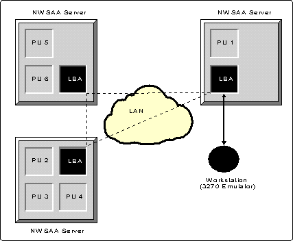
As shown, each server runs a load balancing agent (LBA.NLM) which engages in a sort of internetwork communication with LBAs on other NWSAA servers. Each LBA maintains a table of available PUs and a load factor that is associated with each. The load factor is a calculated value that indicates how busy the server currently is. When a 3270 emulator is loaded at a workstation, it issues a primitive to the nearest LBA on the LAN. The primitive returns a list of available PUs, ordered according to increasing load. The emulator can then walk the list until it finds a PU with an available LU(s) that match the LU(s) it was configured for. It then uses LU(s) on the least busy server for an SNA host connection.
Note: The primitive used for this load balancing process is called CM_CSLIST_GET_II and is included as part of the NWSAA 2.0 Software Developers Kit.
Network Management for NWSAA
NWSAA is typically used in large corporate networks where network management is a paramount issue. NWSAA 2.0 includes two utilities which allow NWSAA servers to be effectively managed:
SAAStatus is the server-based program which allows a user to monitor the status of individual HOST PU profiles, or of NWSAA as a whole.
SAA Services Manager (SSM) is a Windows-based program that runs in conjunction with Novell's Network Management System (NMS) and provides a GUI interface with much greater capabilities than its NetWare counterpart, SAA Status.
Both of these utilities provide services to activate/deactivate PU profiles, monitor SNA data links, monitor LUs, and so on. With SSM, it is possible to set thresholds which cause events to be generated when LU usage reaches a predefined value. SAAStatus is invoked from a server console and is thus constrained to managing a single server; SSM allows management of any number of NWSAA servers from a single networked NMS workstation.
As in previous releases, NWSAA 2.0 also supports IBM's SNA network management architecture and is thus manageable by NetView.
Summary
This AppNote has provided an overview of NetWare for SAA 2.0. For those who might be new to SNA environments, it included a discussion of SNA networks and SNA gateways. To aid in understanding the NWSAA configuration process, the AppNote described the model around which NWSAA 2.0 is designed and provided some example configuration scenarios. It also introduced several of the new features in version 2.0.
As much as we have covered here, there still remains a number of topics that are beyond the scope of this AppNote. The NWSAA product continues to evolve and future releases will undoubtedly contain new features designed to improve the capabilities of interconnecting SNA networks to Novell LANs.
Additional References
The following are suggested readings for more information on the SNA environment:
Systems Network Architecture Technical Overview; IBM (GC30-3073).
System Network Architecture - Concepts and Products; IBM (GC30-3072)
Communications Architecture For Distributed Systems; R.J. Cypser, Addison Wesley.
SAA/LU6.2 Distributed Networks and Applications; John J. Edmunds, McGraw Hill.
* Originally published in Novell AppNotes
Disclaimer
The origin of this information may be internal or external to Novell. While Novell makes all reasonable efforts to verify this information, Novell does not make explicit or implied claims to its validity.