Onsite Network Analysis
Articles and Tips:
01 Apr 1999
It's pretty heavy," I said to the man when he insisted on helping me get my computer bag into the plane's overhead compartment. Unfortunately, the man didn't heed my warning, not realizing that the bag contained a complete cross-platform protocol analysis system--three portable analyzers, cables, a hub, related connectors, and spare cards. Despite my warning, his eyes accused me of tricking him as he writhed in pain after wrenching his back.
My "lethal" bag has exceeded the carry-on weight limitations of many airlines, forcing me to bring a spare backpack to "load balance" computers between the two carry-on bags. Lugging a protocol analysis system gives new meaning to the term load balancing.
I use the protocol analysis system to perform onsite packet-level application analysis, network flow analysis, and protocol analysis. This article outlines a typical onsite analysis session and provides guidelines to help you perform packet-level analysis on a network.
WHY GO TO THE PACKET LEVEL?
I am always amazed that people don't use packet-level analysis as a first-line defense against network problems. By just glancing at the packets that cross the cables, you can solve many problems in a matter of minutes.
For example, once when I was lecturing in Zurich, my European partner Silvia Hagen brought me a trace file from a hospital network. The hospital network had a communication problem: One device at one location was having problems communicating on the network, but all other devices communicated perfectly.
By perusing the trace file, I could see that the auto-frame detection process had gone awry on the malfunctioning device. As a result, this device selected two separate routes and two separate frame types for NetWare Core Protocol (NCP)/IPX and SPX traffic to a server. Unfortunately, the local router that was selected as the proper path did not support the frame type selected for the SPX traffic. (For more information on why you should run, not walk, from auto-frame typing, see the greypaper entitled "Auto-Frame Typing Is Evil" at http://www.netanalysis.org/greypapers.html.)
ONSITE PREPARATION CHECKLIST
Before your network analysis, you should first create an onsite preparation checklist, which ensures that you are performing the most efficient analysis possible during your time onsite. Whether you are analyzing your company's network or a client's network, you should gather the following information before you tap in to the wire:
Basic Network Topology. You should have a network topology map that shows the layout of the network backbone, primary segments, hubs, switches, bridges, and routers. This topology map should also show the number of servers, workstations, and WAN links. In addition, you should have a list of equipment vendors and version numbers, if available.
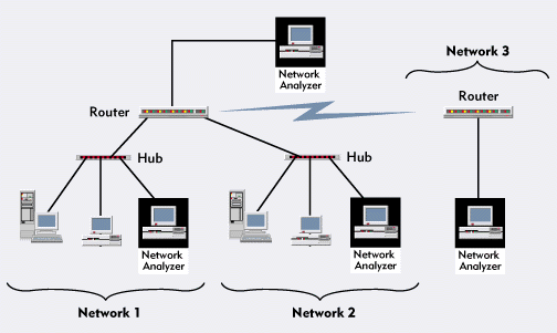
"Tap-in" Points on the Network and Available Network Analyzers. You need to know where you can connect the network analyzer to the network (thereby "tapping in" to the network). An ideal tap-in point is a hub port that services an active workgroup; the hub port should be directly off the network backbone. (See Figure 7.) To identify ideal tap-in points on networks with switches and routers, see Figures 8 and Figures 9. You can mark the tap-in points on the network topology map.
Figure 7: If the network has hubs, you should place the network analyzer as shown above.
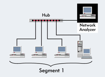
Figure 8: If the network has switches, you should place the network analyzer as shown above.
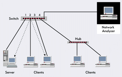
Figure 9: If the network has routers, you should place the network analyzer as shown above.
You should also see if there are any network analyzers onsite and find out their make, model, and version number. You can also take a variety of network analyzers onsite, such as Novell's LANalyzer for Windows (a must-have for NetWare 5 pure IP networks) or Network Associates' Sniffer Basic and Sniffer Pro.
Typical Workstation Configuration. You should know how workstations are configured, including the following information: the type of network interface boards installed in workstations, client settings, version numbers of client software, typical Preferred Servers, and Preferred Tree settings.
Typical Server Configuration. You can use the CONFIG NetWare Loadable Module (NLM) to print a report of the typical server configurations. (For more information about the CONFIG NLM, visit http://support.novell.com, and use Knowledgebase to locate the Technical Information Document [TID] 2941746, "Server Configuration Information.")
List of Network Problems. If you have concerns about the network, you should list these concerns. You should also list errors. For example, if you are analyzing an Ethernet network, are you experiencing media-access control (MAC)-layer errors? What types of errors are occurring? What types of errors are common?
If you are analyzing a Token Ring network, are you experiencing excessive errors that are reported to the ring error monitor? How often do you experience beacons or ring recoveries? Do you have intelligent multistation access units (MSAUs) that can partition off fault domains?
Network Growth Plans. You should predict how the network will grow over the next 12 months. For example, are you adding a Windows NT server? Are you migrating to native IP? Are you planning to upgrade to IPv6? Do you want an all NetWare Link Services Protocol (NLSP) shop, or are you planning to use IPX Routing Information Protocol (RIP) on one or more network segments?
Login Scripts. You need a copy of the active system, container, profile, and user login scripts. You should also print any include statements that are referenced in the login scripts.
NDS Partitioning/Replication. You should print or sketch the Novell Directory Services (NDS) tree and indicate where the replicas are stored.
Traffic Filtering. You should identify any traffic filters (such as socket, port, or firewall filters) that are currently in use or that will be added. If your company is planning to set up a firewall to isolate specific traffic, you should document these plans.
Applications. You should list the applications that users access and the configuration files that run on servers and database servers. In addition, you should document whether or not you are restricting users' access to certain applications (such as games).
Printing Configuration. You should know how network printing is set up. For example, how do remote users print to local printers? A sketch showing the location of print queues, print servers, and remote printers will do.
IP Addressing Configuration. You should document the network's IP configuration. For example, how are IP addresses assigned--manually, via Bootstrap Protocol (BOOTP), or via Dynamic Host Configuration Protocol (DHCP)? Do you plan to create subnets? Are there any address concerns?
Contact List. You should list the people you can contact if you have questions about the network.
WHAT ARE YOU LOOKING FOR?
After completing the checklist, connect the network analyzer to a critical or busy network segment. You can then perform an unfiltered promiscuous mode capture on all traffic, including all protocols and packets. You must capture at least 8 MB of packets in a cyclic buffer (first-in, first-out recycling buffer).
Remember that the data traversing a network is confidential information. If you are providing analysis services to a company, you should be prepared to sign a nondisclosure agreement before you tap in to the company's network. If you let a network analyzer run overnight, you should lock this analyzer in a room or closet. After you document your findings, you should archive, secure, and erase all analysis traces.
For me, the most enjoyable part of doing onsite analysis is the live analysis. With 8 MB or more of packets to peruse, I feel like a kid in a candy store: There's always something interesting to see--each network has its own personality complete with personality quirks. The following list provides a brief overview of what you should look for as you analyze network traces.
General Traffic Patterns. What is the broadcast rate, the multicast rate, and the packets per second rate? You should also check the utilization percentage trend. Which devices are the most active? What is the typical packet size?
Data-Link Errors/Patterns. You should look at the data-link layer (such as Ethernet or Token Ring). Are there any errors? Are there any duplicate packets? Are there any devices that can't transmit on the network?
IPX/SPX Analysis. How much Service Advertising Protocol (SAP) and RIP broadcast traffic is on the network? How much SPX traffic is on the network? How many NetWare Core Protocol (NCP) failures do you see? Evaluate the burst mode traffic: Are burst set sizes gradually increasing? Are there symptoms of auto-frame typing? What is the typical hop count of packets? Is the routing traffic generating NLSP or RIP packets?
TCP/IP Analysis. How much broadcast traffic, such as DHCP and Address Resolution Protocol (ARP) traffic, is on the network? What type of Internet Control Message Protocol (ICMP) traffic is on the network? Are the TCP window sizes adjusting with the network traffic rate or remaining constant? What routing protocols are being used (RIP 1, RIP 2, or Open Shortest Path First [OSPF])? Is there a high number of Domain Naming System (DNS) lookup failures? Are there security issues (such as plaintext passwords)? Are TCP connections terminated properly?
What applications are running on the network? You can identify applications and network processes by their port number. (You can download a list of port numbers here.)
For example, Figure 10 shows an unusual traffic pattern. A device (0x00-60-97-86-17-75) is sending ICMP pings (echo requests) continuously. To identify the device to which the ping packets are directed, look at the packet decode.
Figure 10: ICMP traffic can reveal network design and configuration flaws.
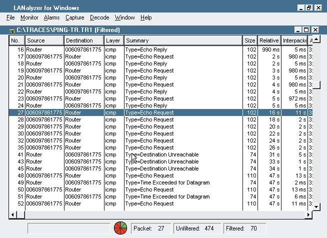
You can see a definite pattern in Figure 10--requests are being sent every second. In packet 27, however, you can see a sudden change in the pattern--the echo requests are not answered. In packet 41, you can see ICMP Destination Unreachable replies. To determine why the packet did not reach its destination, you can look inside the Destination Unreachable replies.
ICMP uses codes to identify the cause of the ICMP reply. For example, the Destination Unreachable replies in Figure 4 show ICMP Type 3, which means the port is unreachable. In other words, the service, process, or application is not running on that system. For example, a DNS query directed to a system that does not support the DNS daemon generates this ICMP response. (You can download more information about ICMP codes here.)
APPLICATION ANALYSIS
Probably the most complex analysis process is application analysis, which requires a painstaking, packet-by-packet review of the application's launch, login, general function set, and unload procedure. If you have never performed application analysis, it can be a daunting task. You may feel that you have thousands of packets and have no idea how to interpret the data. This section explains the process of analyzing an application, interpreting your findings, and documenting these findings.
To analyze an application, complete the following steps:
Identify the procedures that the application performs, and define the stopping points which are created by user interaction. For example, to analyze the process of opening a network file using Word 97, you identify the following procedures: bootup; login/password; launch Word 97; select file > open > filename; and click OK. You then list these procedures on an Application Analysis form. (You can download a sample Application Analysis form here.)
Start the network analyzer, filtering on traffic to and from the test station.
Perform the first procedure listed on the Application Analysis form. Mark the starting and ending packet numbers for the procedure on the form. Pause at least 15 seconds before performing the next procedure.
Perform the next procedure. Again, mark the starting and ending packet numbers. Continue with each procedure, marking the starting and ending packet numbers and pausing 15 seconds between each procedure.
Complete the final procedure, and wait at least 10 minutes. You can then track leftover connections that did not close cleanly.
Document the number of packets required for each procedure and the time elapsed between the first packet and the last packet transmitted during each procedure. Analyzing the data requires you to complete the Application Analysis form--inserting packet counts and process times--as shown in Figure 11.
Figure 11: A completed Application Analysis form
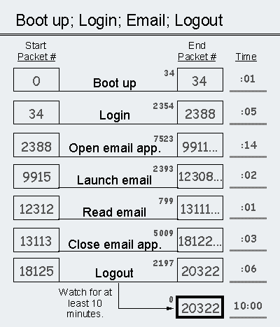
When you have completed the Application Analysis form, you should look at the number of packets each procedure takes and look at the elapsed time of each procedure. Were the results what you expected? Documenting each starting packet and each ending packet in the procedure enables you to separate the procedures and analyze each packet. For example, using Figure 11, you can make the following observations:
Analyze packet count


       short bootup

       2354 login packets

       idle traffic starts

       7523 e-mail launch

       5009 close e-mail


 Analyze time


       login requires time

       slow e-mail launch

       slow logout
To understand what is slowing down the procedures (such as the e-mail launch), you must open the packet file that you captured on the network analyzer. You can then look for the symptoms (such as failures and broadcasts) mentioned earlier in this article. Only by examining the trace at a packet level can you identify what is causing applications to be slow or faulty.
For example, I have discovered the following characteristics about various applications I have analyzed:
The application was not built to run across a network. The application does not cache information and loads and reloads the same file numerous times. The roundtrip latency time between requests and replies is quite long. If you multiply that number by the number of requests, you can see why the application loading process is taking so long.
The application is configured improperly and believes that all of its supplemental files are on the server when they are actually on a local drive.
The application fails to load one of the supplemental files because the user does not have sufficient rights, as shown in the NCP reply to the client's Get Effective Rights request.
The application is too large to load across the WAN. You should move the application to a local drive or server.
The application has a programming fault (a.k.a., a "bug"). An error reply is causing an excessive delay at one point in the application load process.
The application doesn't read files in sequential order, making burst mode useless.
The application uses plaintext passwords and usernames.
The application is a bandwidth hog: Only two users can simultaneously load the application before they consume available bandwidth.
CONCLUSION
As you analyze networks, you will become more familiar with well-behaving applications and poorly behaving applications. If you are a programmer, I urge you to look at the traffic that your application generates on the network. Take the initiative to make the cleanest application possible. If you are a network implementer, consider requiring an application analysis before rolling out any new application.
Laura Chappell is a senior protocol analyst for Network Analysis Institute. You can reach Laura at lchappell@netanalysis.org.
* Originally published in Novell Connection Magazine
Disclaimer
The origin of this information may be internal or external to Novell. While Novell makes all reasonable efforts to verify this information, Novell does not make explicit or implied claims to its validity.