Troubleshooting TCP/IP Networks: Building Your Toolkit
Articles and Tips:
01 Jan 1999
Now that NetWare 5 runs over pure IP, your company may be part of an industry-wide move to IP-only networks. If you are supporting a TCP/IP network, you need a set of troubleshooting tools to identify the problems that can occur on a TCP/IP network. Ideally, you should be able to store these tools on the hard drive of your laptop computer.
As a network analyst, I spend much of my time looking for problems that can occur on a network. On a TCP/IP network, the most common problems center around IP addressing, routing, and connectivity. The tools I use to identify and eradicate TCP/IP network problems include common utilities (such as the utilities included with most TCP/IP stacks), shareware and freeware utilities, off-the-shelf applications, and network analyzers.
Before you can identify problems on a TCP/IP network, you must understand the TCP/IP communications process. This article explains how this communications process works and then describes how you can use the utilities included with most TCP/IP stacks to troubleshoot problems. (A future article will feature shareware and freeware utilities and off-the-shelf applications.)
TCP/IP COMMUNICATIONS OVERVIEW
Figure 2 shows a simple internetwork that contains two separate networks. Suppose a user on network 130.59.0.0 typed the following command to begin a file transfer to the CORPFS1 server:
Figure 2: Communicating across an IP-only network
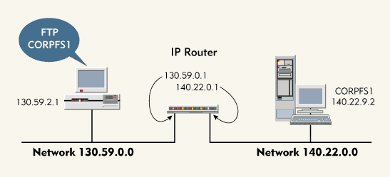
FTP CORPFS1
The workstation must convert this command into a valid packet to establish an FTP connection to the server. This packet must contain the destination port number, destination IP address, and destination Media Access Control (MAC) layer address.
To create an IP packet and to transmit this packet to an FTP server on the internetwork, the workstation must complete the following steps. (See Figure 3.)
Figure 3: The TCP/IP communications process
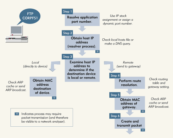
Step 1. Resolve the application port number.
The workstation must convert the FTP command into a port number. The workstation's TCP/IP stack maintains a list of port numbers that define the most common TCP/IP functions or applications. (For a list of assigned port numbers, read Request for Comments [RFC] 1700 at http://www.rfc-editor.org/rfc.html.) If the appplication doesn't have an assigned port number that is known to the workstation's TCP/IP stack, it may use a dynamic port number.
The port number for FTP commands is 21; the port number for FTP data exchange is 20. Because the user typed an FTP command, the workstation addresses the packet to port 21.
Step 2. Obtain the host IP address.
To create an IP header that can be used to route a packet to another device on the internetwork, the workstation must resolve the name, CORPFS1, to a host IP address. To resolve this name, the workstation would first check in cache: If the workstation had made a previous request to the CORPFS1 server, the host IP address would be buffered in cache.
If the host IP address were not in cache, the workstation would then check its local drive to see if a hosts file existed. To speed up the name resolution process, you can create a hosts file, which contains a table of host names and their IP addresses, and store this file on the workstation's hard drive. If the workstation did not have a hosts file or if this file did not contain the host IP address for the CORPFS1 server, the workstation would check to see if it were configured to use a Domain Naming System (DNS) server. If the workstation had a DNS server, the workstation would query the DNS server for the host IP address of the CORPFS1 server.
The DNS server would send a reply packet that contained the host IP address of the CORPFS1 server. The workstation would then have enough information to build an IP packet header.
Note: If the DNS server did not send a reply packet, the workstation would send a second query before trying the next DNS server listed for this workstation (if another DNS server were listed). Workstations usually try each DNS server listed until they receive a reply or run out of DNS servers to query.
Step 3. Examine the host IP address to determine if the destination device is local or remote.
The workstation must then address the packet to the appropriate device or to a gateway (router). If the CORPFS1 server and the workstation were on the same network, the workstation could address the MAC layer of the packet directly to the hardware address of the CORPFS1 server. If the CORPFS1 server and the workstation were not on the same network, the workstation would address the packet to a gateway.
How would the workstation know if a server were local or remote? The workstation would apply its network mask to the server IP address and compare its network address to the server network address. For example, the workstation would compare the following information:
Workstation IP Address: 130.59.2.1
Workstation Network Mask: 255.255.0.0
Workstation Network Address: 130.59.0.0
Server IP Address: 140.22.9.2
Workstation Network Mask: 255.255.0.0
Server Network Mask: 140.22.0.0
Because the workstation network address and the server network address did not match, the workstation would have to resolve the route to the CORPFS1 server by sending a packet to a gateway.
If the CORPFS1 server were located on the local network, the workstation would use the Address Resolution Protocol (ARP) to resolve the IP-to-Ethernet address. This process is explained in Step 6, since the workstation must use this same technique to obtain the Ethernet address of the gateway.
Step 4. Perform route resolution.
Once the workstation knew that the CORPFS1 server were on a remote network, the workstation would perform route resolution to determine which direction to send the packet. In this process, the workstation would examine its routing tables to determine if these tables contained one of the following:
The complete host IP address of the CORPFS1 server
The network address for the CORPFS1 server
If the routing tables did not contain this information, the workstation would check for a default gateway. For example, the workstation in Figure 2 has a default gateway, which has an IP address of 130.59.0.1.
Step 5. Obtain the MAC address of the gateway.
Even with the host IP address of the gateway, the workstation would still not have enough information to create and send the packet. To add the last header to the packet, the workstation must know the MAC address of the gateway.
Because the workstation and the gateway in Figure 2 are connected to an Ethernet network, the workstation must create an Ethernet packet header. The workstation would send an ARP broadcast requesting the MAC address of the device (the gateway) that uses the IP address 130.59.0.1. The gateway would reply to this packet, supplying its MAC address in the ARP response.
The workstation would then know the MAC address of the gateway, the host IP address of the CORPFS1 server, and the destination port number for FTP commands.
Step 6. Create and transmit the packet.
Finally, the workstation could create and transmit the packet.
PROBLEMS, PROBLEMS, PROBLEMS
By understanding how a workstation creates and transmits a packet, you can identify the step a workstation is performing when an error occurs. The steps marked with an asterisk (*) in Figure 2 indicate when the workstation might need to transmit a packet on the network. For example, the workstation may need to send a DNS query or an ARP broadcast.
Knowing when the workstation may need to send a packet and using a network analyzer to track what the workstation actually does is an extremely effective troubleshooting method: You can determine what steps a workstation has completed successfully and identify a relationship between the information contained in the packets sent and the processes that occurred at the workstation.
For example, suppose a workstation sent ARP broadcasts requesting a local device's hardware address, and the requests were unanswered. In this case, you could assume that the workstation had resolved the application port number, obtained the destination IP address, and determined the route (local) to the destination. If you were troubleshooting this problem, you could investigate several possible causes:
The workstation might not have performed the route resolution process properly, and the destination device might actually be on another network.
The workstation might have received incorrect DNS information.
The destination device is not available.
A numer of problems can occur in the TCP/IP communications process. Some common problems are listed below.
The workstation does not have a working TCP/IP stack and is, therefore, unable to transmit packets.
The workstation is not using the right frame type and, therefore, cannot locate any network services.
The destination device does not support the desired service. As a result, the port number is unreachable.
The workstation does not have a DNS entry or a hosts file and is, therefore, unable to resolve host names.
The workstation has an invalid entry in its hosts file. As a result, the workstation resolves the name to the wrong IP address.
The DNS server has an invalid entry in its hosts file. As a result, the DNS server resolves the name to the wrong IP address.
The workstation has a DNS entry for a device that does not support DNS. As a result, the port number is unreachable.
No DNS servers are available at this time. As a result, the workstation cannot resolve host names.
The DNS servers are unable to identify an address for the host and are, therefore, unable to resolve the host name.
The workstation has the wrong network mask. As a result, the workstation determines the wrong destination location.
The workstation has an incorrect route in its routing tables. As a result, the workstation sends packets in the wrong direction.
No route is known, and the default gateway is not available. As a result, the packet is dropped.
The default gateway does not have the correct routing tables. As a result, the packet is sent in the wrong direction.
The workstation has an incorrect entry in its ARP cache and, therefore, sends the packet to the wrong MAC address.
The workstation gets no response to an ARP broadcast and, therefore, cannot resolve a MAC address.
These types of problems can occur with just a simple request to establish an FTP connection.
THE TROUBLESHOOTING TOOLS
When you enable the TCP/IP stack on a Windows 98 or Windows 95 workstation, a set of TCP/IP troubleshooting utilities are loaded into the Windows directory on the workstation's hard drive. These utilities include the following:
The Packet Internet Grouper (PING) utility
The Trace Route (TRACERT) utility
The ARP utility
The ROUTE utility
The NETSTAT utility
The WINIPCFG utility
The PING Utility
You can use the PING utility to query another IP device on the network to determine if the IP device is "alive" and how long it takes a packet to reach the device. This utility is one of the first tools you should use if the problem appears to be caused by a lack of connectivity between IP devices. The PING utility uses Internet Control Message Protocol (ICMP) echo packets to perform tests on the network.
You use the following syntax to launch the PING utility:
PING [-t] [-a] [-n count] [-l size] [-f] [-i TTL] [-v TOS] [-r count] [-s count] [[-j host-list] | [-k host-list]] [-w timeout] destination-list
The parameters are explained below:
|
-t |
Use this parameter to ping the host continuously. (Be careful not to overload the network.) To stop this test, press <Ctrl< C. |
|
-a |
Use this parameter to resolve addresses to host names. |
|
-n |
count Use this parameter to determine the number of echo requests to send. |
|
-l |
size Use this parameter to determine the ping packet size. |
|
-f |
Use this parameter to set the Don't Fragment flag on the packet. This flag ensures that the packet is sent to the destination device in its entirety. If you set this flag, routers will be unable to fragment the packet to cross media that support smaller packet sizes. If a route includes such media, a router discards the packet and sends an ICMP destination unreachable packet to the sender. |
|
-i |
TTL Use this parameter to set the Time To Live (TTL) flag, which indicates the number of routers (hops) that a packet may cross. To limit the distance an ICMP echo packet can travel, you should define a small TTL value. |
|
-v |
TOS Use this parameter to set the Type Of Service (TOS) flag. If the network has been configured to support TOS, you can force the PING utility to use a specific type of service for the connectivity test. |
|
-r |
count Use this parameter to record the number of hops to the destination IP device. |
|
-s |
count Use this parameter to timestamp the hops. |
|
-j |
host-list Use this parameter to test loose source route along host list. This test specifies certain devices a packet must cross to reach a destination. This test does not specify the exact route, which can include other devices. |
|
-k |
host-list Use this parameter to test strict source route along host-list. This test specifies all the devices a packet must cross to reach a destination. The packet cannot cross other devices. |
|
-w |
timeout Use this parameter to set the timeout in milliseconds. The timeout determines how long the IP device waits for a reply. |
If a device is having problems communicating on the network, enter the following command at the DOS prompt:
PING 127.0.0.1
The address 127.0.0.1 is the loopback address. If you enter this command, the device pings its own TCP/IP stack. If the device can't see its own TCP/IP stack, the device can't communicate on the network.
Note: Note: The Windows TCP/IP stack places an identifying pattern in each device's ping packets. This identifying pattern, which is typically the alphabet, is located inside the ping packet padding area. You can use this identifying pattern to determine if a device is using the Windows TCP/IP stack.
You should not use the -t parameter unless you want to track and manually terminate the ping test. This parameter causes a continuous transmission of ping packets and may generate significant traffic on the network.
If you want to test the maximum packet size supported between two devices, use the -l parameter (to define the maximum packet size) with the -f flag (to prevent the fragmentation of the packet). For example, if you wanted to know if you could send a 4 KB packet from a workstation to a NetWare 5 server in another building, you would enter the following command:
ping -f -l 4096 [destination]
You could then send the 4 KB packet to the server and find out if and where the packet would need to be fragmented.
The TRACERT Utility
You can use the TRACERT utility to determine the route that a packet may take to get from one device to another (if a route exists). You can also use this utility to determine the time that it takes the packet to reach routers and to identify sluggish spots on the route.
The TRACERT utility uses interesting technology. If you analyze packets sent by the TRACERT utility, you will find that it uses the TTL counter to locate the route to another device.
When you run the TRACERT utility, it instructs the workstation to send a packet with a TTL count of 1 to the destination device. When this packet reaches the local router, it discards the packet because the router cannot decrement the TTL count to 0 and forward the packet. The router then sends an ICMP destination unreachable packet to the workstation.
This reply packet gives the workstation the IP address of the first router in the route. The workstation then sends the same packet with a TTL of 2. The local router decrements the TTL count to 1 and forwards the packet.
The next router cannot decrement the TTL count to 0 and forward the packet, so this router sends an ICMP destination unreachable packet back to the workstation. This reply packet provides the IP address of the second router in the route.
The workstation continues incrementing the TTL count on each successive transmission until the workstation receives a reply back from the destination device.
You use the following syntax to launch the TRACERT utility:
tracert [-d] [-h maximum_hops] [-j host-list] [-w timeout] target_name
The parameters are explained below:
|
-d |
Use this parameter if you do not want to resolve addresses to host names. |
|
-h |
maximum_hops Use this parameter to determine the maximum number of hops to search for. |
|
-j |
host-list Use this parameter to test loose source route along host list. This test specifies certain devices a packet must cross to reach a destination. This test does not specify the exact route, which can include other devices. |
|
-w |
timeout Use this parameter to determine timeout in milliseconds. Timeout determines how long the device waits for each reply. |
You should be careful when using the TRACERT utility. If a network supports load balancing (as the Internet does, for example), a router may send the first packet of a test via one route and the next packet via another route. For example, in Figure 4, the workstation is tracing the route to 150.20.20.1. Router A load balances between its two routes to the destination network 150.20.20.0. The process proceeds as follows:
Figure 4: If a network performs load-balancing, using the TRACERT utility to determine the best route may produce conflicting results.
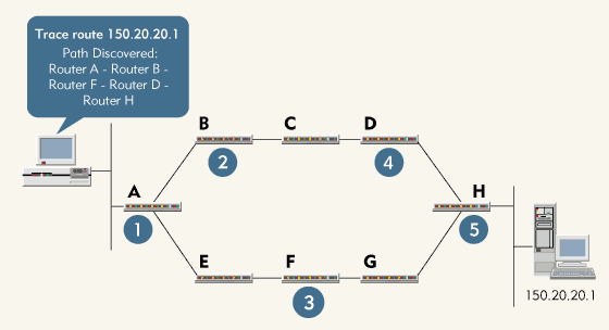
Step 1. The workstation sends a packet with a TTL of 1 to Router A. Router A discards the packet and sends an ICMP destination unreachable packet to the workstation. The TRACERT utility determines that Router A is the first router in the route.
Step 2. The workstation sends a packet with a TTL of 2 to Router A, which forwards the packet with a TTL of 1 to Router B. Router B discards the packet and sends an ICMP destination unreachable packet to the workstation. The TRACERT utility determines that Rout-er B is the second router in the path.
Step 3. The workstation sends a packet with a TTL of 3 to Router A. Since Router A is performing load balancing, it forwards the packet with a TTL of 2 to Router E this time. Router E forwards the packet with a TTL of 1 to Router F. Router F discards the packet and sends an ICMP destination unreachable packet to the workstation. The TRACERT utility determines that Rout-er F is the third router in the route.
Step 4. The workstation sends a packet with a TTL of 4 to Router A. Since Router A is performing load balancing, it forwards the packet with a TTL of 3 to Router B this time. Router B forwards the packet with a TTL of 2 to Router C, and Router C forwards the packet with a TTL of 1 to Router D. Router D discards the packet and sends an ICMP destination unreachable message to the workstation. The TRACERT utility determines that Router D is the fourth router in the route.
Step 5. The workstation sends a packet with a TTL of 5 to Router A. Router A forwards the packet with a TTL of 4 to Router E. Router E forwards the packet with a TTL of 3 to Router F. Router F forwards the packet with a TTL of 2 to Router G. Router G forwards the packet with a TTL of 1 to Router H. Router H discards the packet and sends an ICMP destination unreachable packet to the workstation. The TRACERT utility determines that Router H is the fifth router in the route.
Step 6. The workstation sends a packet with a TTL of 6 to Router A. Router A forwards the packet with a TTL of 5 to Router B. Router B forwards the packet with a TTL of 4 to Router C. Router C forwards the packet with a TTL of 3 to Router D. Router D forwards the packet with a TTL of 2 to Router H. Router H forwards the packet with a TTL of 1 to the destination device. The destination device responds to the workstation.
From this test, the route would appear to be A-B-F-D-H--an impossible path.
The ARP Utility
If you need to resolve an IP-to-Ethernet address, you can use the ARP utility to view a local device's ARP cache and to force an ARP broadcast. You should use the ARP utility if you doubt the validity of a device's local ARP cache or if you want to determine how entries are being added to the cache. You can also use the ARP utility to manually add an entry to the ARP cache or delete an incorrect entry.
You use the following syntax to launch the ARP utility:
ARP -a [inet_addr] [-N if_addr]


 ARP - s inet_addr eth_addr [if_addr]


 ARP - d inet_addr [if_addr]
The parameters are explained below:
|
-a |
Use this parameter to display the entries in the ARP tables. If more than one network interface board uses ARP, entries for each ARP table are displayed. If you include the inet_addr parameter, the ARP utility displays the IP and physical address for only the specified device. |
|
inet_addr |
Use this parameter to specify an internet address. |
|
-N if-addr |
Use this parameter to display the ARP entries for the network interface board specified by the if_addr parameter. |
|
-d |
Use this parameter to delete the host specified by the in_addr parameter. |
|
-s |
Use this parameter to add host to the ARP table and to associate the host's Inter-net address (specified by the inet_addr parameter) with its physical address (specified by the eth_addr parameter). The physical address is expressed as 6 hexadecimal bytes separated by hyphens. The entry added to the ARP table is permanent. |
|
eth_addr |
Use this parameter to specify a physical address. |
|
if_addr |
Use this parameter to specify the Internet address of the network interface board whose ARP table should be modified. If you do not use this parameter, the ARP utility will modify the ARP table of the first applicable network interface board. |
The ROUTE Utility
When considering how to route packets to a remote destination, a device first checks its local routing tables. You can use the ROUTE utility to manually add entries to the routing table; however, devices usually learn routes dynamically from the network. For example, in Figure 5, Ginny sends a ping packet to Drake. The TCP/IP stack on Ginny's workstation checks its routing table for Drake's host address (204.10.11.5). If the routing table does not include an entry for this host address, the workstation checks its routing table for a network entry (204.10.11.0).
Figure 5: On a TCP/IP network, devices learn routes dynamically.
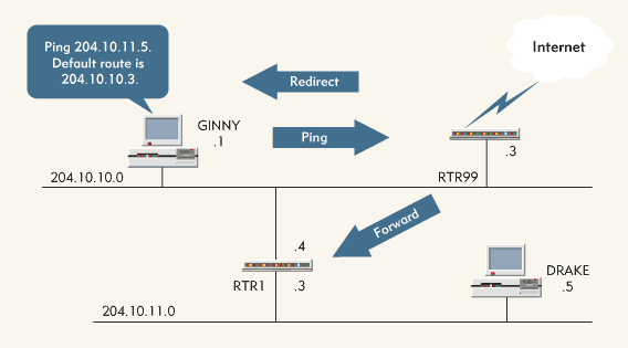
If the routing table does not include an entry for the network, the workstation checks for a default gateway. In this case, Ginny's workstation has a default gateway (204.10.10.3) to the Internet.
Unfortunately, this gateway is not the best route to network 204.10.11.0. However, Ginny's workstation does not know the gateway is not the best route and sends the packet to the default gateway.
The default gateway returns an ICMP packet to the workstation. Called a redirection message, this ICMP packet indicates that a better route is available through router 204.10.10.4. Ginny's workstation uses this ICMP packet to update its routing tables. The next time Ginny sends a packet to Drake, Ginny's workstation will find a network entry for 204.10.11.0 in the routing tables, indicating that the workstation should forward the packet to router 204.10.10.4.
Note: Note: If a device receives redirect messages for most of the devices it tries to communicate with, the default gateway specified may not be the most appropriate gateway for that device.
You use the following syntax to launch the ROUTE utility:
ROUTE [-f] [command [destination] [MASK netmask] [gateway]
The parameters are explained below:
|
-f |
Use this parameter to clear all of the gateway entries in the routing table. If you use this parameter in conjunction with one of the commands, the routing table is cleared before the command is run. |
|
command |
Use this parameter to specify one of four commands: The PRINT command prints or displays a route. The ADD command adds a route. The DELETE command deletes a route. The CHANGE command modifies an existing route. |
|
destination |
Use this parameter to specify the host to which the device should send the command. |
|
MASK |
Use this parameter if you want the next parameter to be interpreted as the netmask parameter. |
|
netmask |
Use this parameter to associate a subnet mask with a route entry. If you do not include this parameter, the default subnet mask is 255.255.255.255. |
|
gateway |
Use this parameter to specify a gateway. |
To view the routing tables on a device, type the following command at the DOS prompt:
ROUTE PRINT
If you want to force the device to rebuild its routing tables because the device is sending packets to the wrong router, you should use the -f parameter. If you use the PRINT or DELETE command, you can use wildcards for the destination device and gateway, or you can omit the gateway parameter.
The NETSTAT Utility
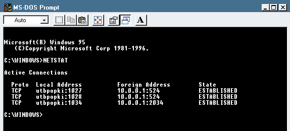
You can use the NETSTAT utility to obtain information about the current protocol operations for TCP/IP connections. For example, suppose you established an FTP connection to a server and then left your workstation. When you returned, you could use the NETSTAT utility to determine whether or not your connection was still valid.
The NETSTAT utility shows statistics for TCP, User Datagram Protocol (UDP), ICMP, and IP. Figure 6 shows the information the NETSTAT utility would collect from a NetWare 5 pure IP workstation that has made a connection to a NetWare 5 server. The 524 port number is assigned to NetWare Core Protocol (NCP) connections. (For more information about pure IP communications on a NetWare 5 network, see "Migrating to Pure IP With NetWare 5," NetWare Connection, Sept. 1998, pp. 34-37. You can download this article from http://www.nwconnection.com/sep.98/migra98.)
Figure 6: Information collected by the NETSTAT utility
You use the following syntax to launch the NETSTAT utility:
NETSTAT [-a] [-e] [-n] [-s] [-p proto] [-r] [interval]
The parameters are explained below:
|
-a |
Use this parameter to display all connections and listening ports. A listening port identifies a process that is running on a device. For example, if a device supports FTP, which uses ports 20 and 21, these ports will be displayed. |
|
-e |
Use this parameter to display Ethernet statistics. You can use this parameter in conjunction with the -s parameter. |
|
-n |
Use this parameter to display addresses and port numbers in numerical form. |
|
-s |
Use this parameter to display protocol statistics. By default, statistics are shown for TCP, UDP, and IP. You can use the -p proto parameter to display statistics for only one protocol. |
|
-p proto |
Replace proto with TCP, UDP, or IP to view connections for a particular protocol. You can use this parameter in conjunction with the -s parameter to display statistics for a particular protocol. |
|
-r |
Use this parameter to display the routing table. |
|
interval |
Use this parameter to redisplay selected statistics. Replace interval with the number of seconds the NETSTAT utility should pause between each display. Press <CTRL< C to quit the NETSTAT utility. |
You can use the -r parameter to display routing tables. If you want to watch information be updated dynamically as connections are established and terminated, you should use the interval parameter. For example, you would enter the following command to see the statistics updated every 5 seconds:
NETSTAT 5
The WINIPCFG Utility
You can use the WINIPCFG utility to check a workstation's configuration details. For example, you can use the WINIPCFG utility to view the following information:
Current host hardware address
IP address
IP address lease and renewal times (for DHCP [Dynamic Host Configuration Protocol]-assigned addresses)
Default gateway configuration
If your network is experiencing DHCP address problems, you can use the WINIPCFG utility's Renew/Renew All feature to force a workstation to attempt to renew an assigned address. When you use this feature, however, the workstation releases its IP address and cannot continue any IP-based operations.
CONCLUSION
If you are supporting a TCP/IP network, the utilities mentioned in this article can provide the first level of network analysis and can be found on almost any Windows workstation. After you understand TCP/IP communications and become familiar with these utilities, you should be able to troubleshoot most common TCP/IP communications problems.
Laura Chappell is a senior protocol analyst for Network Analysis Institute. She provides onsite and offsite network analysis as well as training on troubleshooting and optimization techniques. Laura is presenting two sessions on TCP/IP troubleshooting and communications at BrainShare '99 in Salt Lake City. Her e-mail address is lchappell@netanalysis.org.
* Originally published in Novell Connection Magazine
Disclaimer
The origin of this information may be internal or external to Novell. While Novell makes all reasonable efforts to verify this information, Novell does not make explicit or implied claims to its validity.