NetWare Link Services Protocol: Interoperating With RIP and SAP
Articles and Tips:
01 Nov 1997
This article is the final part of a three-part series that focuses onNetWare Link Services Protocol (NLSP), Novell's default routing protocolfor IntranetWare and NetWare 4.11. The first article in this series explainedhow NLSP devices create a link state database, which is essentially a mapof the entire network. (See "NetWareLink Services Protocol: Building a Link State Database",NetWareConnection, Sept. 1997, pp. 38[shy ]45.) The second article describedhow NLSP devices update the link state database and how you can change NLSPparameters. (See "NetWare LinkServices Protocol: Updating the Link State Database",NetWareConnection, Oct. 1997, pp. 34[shy ]39.) The third article explains howNLSP devices interoperate with Routing Information Protocol (RIP) and ServiceAdvertising Protocol (SAP) devices (such as NetWare 4.1, NetWare 3.11, andNetWare 2.2 servers).
Although IntranetWare and NetWare 4.11 use NLSP, IntranetWare and NetWareclients use RIP and SAP to locate many services on a network. An NLSP devicemust reply to a client's RIP or SAP lookup request if the NLSP device knowsthe route to a particular network and considers itself part of the bestroute. In addition, an NLSP device may exist on a network that supportsa RIP device. As a result, an NLSP device must use RIP and SAP to performthe following tasks:
To reply to certain RIP or SAP requests
To absorb SAP information for local services
SENDING AND RECEIVING RIP INFORMATION
NLSP routers are intelligent and incredibly flexible in mixing and matchingrouting protocols. If an NLSP device detects that a RIP router is broadcastingRIP information on the local circuit, the NLSP device automatically beginssending RIP information to the RIP device, thereby maintaining backwardcompatibility. (Acircuitis a logical connection to the network.)For example, in Figure 1, the MPR1 router isa RIP/SAP device, and the CORP-FS router is an NLSP device.
Figure 1: NLSP devices and RIP devices can exist on the same network.
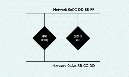
When an NLSP device learns about a network through RIP, the device absorbsthe RIP information as an Xroute, or external route. The distance of Xroutesare described in hops and ticks. (A RIP device assumes that it takes onetick--approximately 1/18th of a second--to cross any network segment.)
Although an NLSP device stores Xroute information in its link state database,only the designated router includes this information in its Link State Protocol(LSP) packet. (Each network has onedesignated router, which helpsthe other NLSP devices maintain a map of the entire network.) For example, Figure 2 shows CORP-FS's LSP packet, which includesXroute information for networks 0x00-11-11-11 and 0xAA-BB-CC-DD.
Figure 2: Only designated routers include Xroute information in LSP packets.
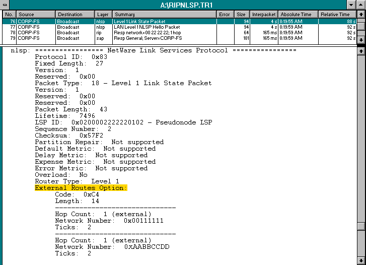
If an NLSP device detects a RIP router on the local network, the NLSPdevice automatically sends RIP and SAP update packets. By default, an NLSPdevice sends these update packets every 60 seconds, but you can use theINETCFG utility to change this time interval.
FORWARDING PACKETS ON A MIXED NETWORK
When an NLSP device forwards packets on a network that includes bothNLSP routes and RIP routes, the NLSP device adheres to the following rules:
The NLSP device uses an NLSP-only route if one exists.
If an NLSP-only route does not exist, the NLSP device uses only the RIP portion of the route.
If more than one route exists, the NLSP device uses the RIP route with the lowest number of ticks.
If more than one route exists and the tick count is equal, the NLSP device uses the RIP route with the lowest hop count.
If both the tick count and the hop count are equal, the NLSP device examines the NLSP portion of the route (if one exists) to determine which route has the lowest cost.
If the tick count, the hop count, and the cost are the same for both routes, the NLSP device uses either route.
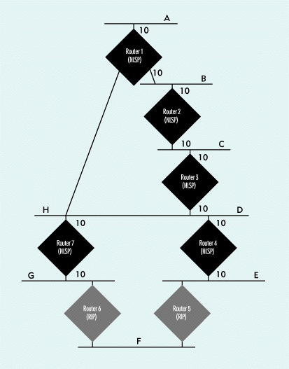
For example, Figure 3 shows two routes fromnetwork A to network F. Router 1, which is an NLSP device, knows that pseudonodeE and pseudonode G are connected to network F. (A pseudonode is avirtual device that represents the network.) Because there is no NLSP-onlyroute, Router 1 first considers the tick counts between the two pseudonodesand network F. The tick counts are equal, so Router 1 considers the hopcounts, which are also equal. Router 1 then considers the NLSP routes fromA to G and A to E. The NLSP route through Router 1 and Router 7 has a costof 20. Since this route has the lower cost, it is the better route. (Formore information about costs, see "NLSP VersusRIP".)
Figure 3: Finding the best route from network A to network F
SENDING AND RECEIVING SAP INFORMATION
When an NLSP device receives SAP information, the device absorbs thisinformation into its link state database. The NLSP device then sends SAPupdate packets every 60 seconds by default.
An NLSP device also propagates SAP information through LSP packets, asshown in Figure 4. LSP 0x02-00-00-22-22-22-01-01indicates that two services are available on network 0x00-11-11-11: a NovellDirectory Services (NDS) server in TREE1 and the MPR1 router.
Figure 4: SAP information is propagated across the network in both SAP packets and LSP packets.
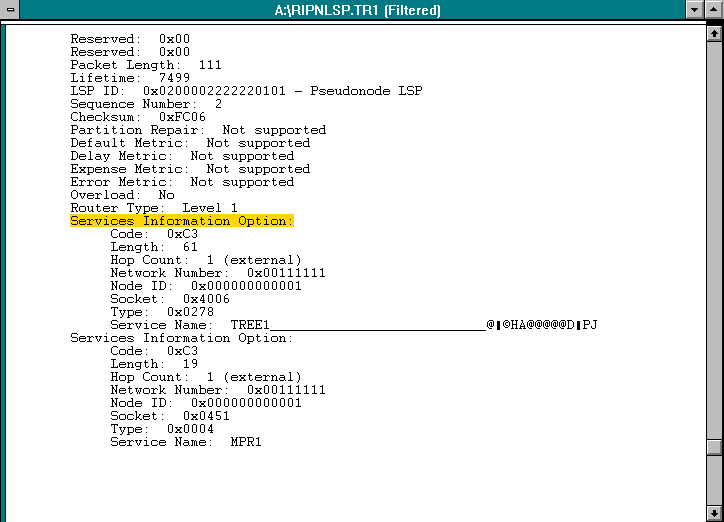
SAP information is associated with the network on which the SAP deviceresides. If an NLSP device does not know a route to a network, the NLSPdevice will not send SAP information for any services on that network.
BUILDING A RIP ROUTE
If an NLSP device detects a RIP network on one side and an NLSP networkon the other side, the NLSP device must send both NLSP information and RIPinformation. When the NLSP device sends RIP broadcast packets, this devicemust convert entries from its link state database into information thatcan be used by RIP devices. To convert the entries, the NLSP device mustcomplete the following tasks:
Attach a Hop Count to an LSP Entry
Each NLSP device uses a decision-making process to determine the bestroute on a network. If the NLSP device is sending RIP packets, this devicedetermines a hop count for NLSP routes as part of the decision-making process.(An NLSP device uses its knowledge of the network to determine the hop count.)The NLSP device includes this hop count in the RIP and SAP packets sentonto the RIP network.
Attach a Tick Count to an LSP Entry
Determining a tick count is a bit more difficult. Each time an NLSP devicereceives an LSP packet, the NLSP device automatically determines a tickcount based on the NLSP delay and throughput values included in the LSPpacket.
The NLSP device uses the following calculation for a LAN:
MAX [ 1, (576 x 8 x 18 /throughput) + (delay x 18 / 1,000,000) ]
For example, a typical throughput value for a 10 Mbit/s Ethernet networkwould be 10 million, and a typical delay value would be 200. You could usethe following calculation to determine the tick count based on these values:
MAX [ 1, (576 x 8 x 18 / 10,000,000) + (200 x 18 / 1,000,000) ]
For this calculation, the tick count is 1. Of course, a network withlower throughput would have a higher tick count, thus ensuring that thebest route is based on actual performance.
The NLSP device uses the following calculation for a WAN:
MAX [ 1, (576 x 64 x 18 / throughput) + (2 x delay x 18 / 1,000,000) ]
As with the LAN calculation, you would calculate the tick count and thehop count based on the WAN's throughput value and delay value, which variesaccording to the speed of the WAN.
FILTERING RIP AND SAP PACKETS
As you may know, you can filter RIP and SAP packets to reduce broadcasttraffic on a RIP network. You cannot, however, filter RIP and SAP informationon an NLSP network: If an NLSP device detects a RIP network or a SAP service,the device propagates RIP and SAP information through LSP packets.
By default, an NLSP device stops sending RIP and SAP information on alink after the device quits receiving RIP and SAP information from otherdevices. The NLSP device simply waits until the RIP and SAP Xroute entrieshave timed out of the link state database and then sets the RIP and SAPstate to Off. (Thestateis the mode in which a router is currentlyoperating.)
If the RIP and SAP state is set to On, the NLSP device is a RIP/SAP-onlyrouter. If the RIP and SAP state is set to Off, the device is an NLSP-onlyrouter. If the RIP and SAP state is set to Auto, the NLSP device sends RIPand SAP broadcasts to provide backward compatibility with any RIP and SAPdevices that might appear on the network. You can manually stop an NLSPdevice from sending RIP and SAP packets by changing the device's RIP andSAP state to Off.
CONCLUSION
Because NLSP devices automatically recognize and participate in the exchangeof RIP and SAP information, you can slowly migrate your company's networkto NLSP. For more information about migrating from RIP and SAP to NLSP,see"Novell's Guide to NLSP Migration,"which is included in theNetWare 4.11 Communications section in the IntranetWare and NetWare 4.11documentation.
Understanding how NLSP works with RIP and SAP can help you troubleshootand optimize your company's network. As always, I strongly recommend thatyou purchase a network analyzer, which shows you what's happening on thenetwork.
Laura Chappell researches, writes, and lectures on TCP/IP and IPX/SPXprotocol performance, troubleshooting, and optimization. She speaks at NetWareConferences and presents customized training courses on network analysis.You can reach Laura at lchappell@imagitech.com.
NLSP Versus RIP
To understand the differences between NetWare Link Services Protocol (NLSP) and Routing Information Protocol (RIP), you must compare how NLSP devices determine the best route to send a packet with how RIP devices determine the best route. A RIP device assumes that it takes one tick (approximately 1/18th of a second) to cross any network segment. For example, Router 1 in Figure 5 would determine that the FS1 server's internal IPX network was six ticks away from Fred's workstation through path 1. Router 1 would also determine that the FS1 server's internal IPX network was five ticks away from Fred's workstation through path 2.
Figure 5: RIP devices assume that it takes one tick to cross a LAN.
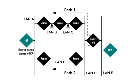
If Fred sent packets addressed to the FS1 server's internal IPX address, which path would Router 1 use when routing these packets? Router 1 would send Fred's packets through path 2 because this RIP device defined path 2 as only five ticks away.
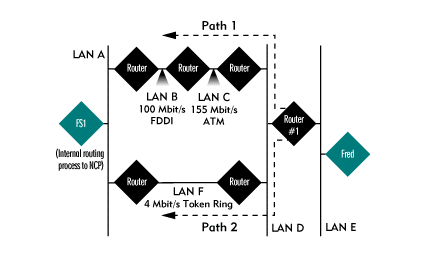
In reality, however, path 1 is probably faster than Path 2. LAN B is a 100 Mbit/s Fiber Distributed Data Interface (FDDI) ring network, LAN C is a 155 Mbit/s Asynchronous Transfer Mode (ATM) network, and LAN F is a 4 Mbit/s Token Ring network. (See Figure 6.) Because path 1 includes a 100 Mbit/s network and a 155 Mbit/s network, this path is probably much faster than crossing the 4 Mbit/s network of path 2.
Figure 6: Path 1 has an FDDI network and an ATM network.
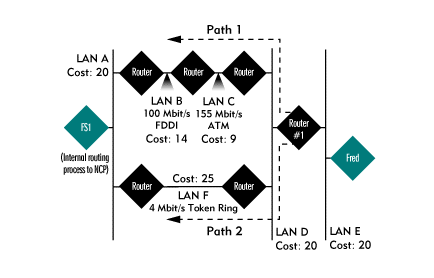
Instead of using a tick count, NLSP devices use costs, which are metric values used to differentiate links based on their available throughput. A slower link has a higher cost than a faster link, and the best route has the lowest cost from end to end. Using default costs, an NLSP device would determine that path 1 was the better route and send packets through path 1. (See Figure 7.)
Figure 7: For NLSP devices, path 1 is the best route.
* Originally published in Novell Connection Magazine
Disclaimer
The origin of this information may be internal or external to Novell. While Novell makes all reasonable efforts to verify this information, Novell does not make explicit or implied claims to its validity.