NetWare Link Services Protocol: Updating the Link State Database
Articles and Tips:
01 Oct 1997
This article is the second part of a three-part series that presentsa packet-level view of NetWare Link Services Protocol (NLSP), Novell's defaultrouting protocol for IntranetWare and NetWare 4.11. The first article inthis series explained how NLSP devices use hello packets and Link StateProtocol (LSP) packets to create a map of the entire network. This map iscalled thelink state database.(See "NetWareLink Services Protocol: Building a Link State Database",NetWareConnection, Sept. 1997, pp. 38[shy ]45.) The second article in this seriesexplains the following:
How NLSP devices update the link state database when changes occur on the network
How to change NLSP parameters
KEEPING IN TOUCH
As explained in the last issue ofNetWare Connection, NLSP devicesbuild the link state database by exchanging hello packets and LSP packets.By default, each NLSP device transmits an LSP packet approximately everytwo hours. This LSP packet contains information about the NLSP device'slinks, services, and external routers. For example, an LSP packet transmittedby an IntranetWare server would include information such as the servicesthe server provides and its internal and external IPX addresses.
Each NLSP device uses a unique identification number called anLSPID numberto identify all of the device's LSP packets. To uniquely identifyLSP packets, the NLSP device increments the sequence number in each LSPpacket, whether or not other information has changed since this device sentits last LSP packet.
The higher the sequence number is, the more up-to-date the informationin the LSP packet is. For example, suppose that the CORP-FS router wererunning on a network on which few changes were made. If the CORP-FS routertransmitted an LSP packet with sequence number 4 at 8 a.m., this routerwould transmit an LSP packet with sequence number 5 at approximately 10a.m. Both LSP packets would contain the same LSP ID number, such as LSPID number 0x02-00-00-22-22-22-00-00.
If you were to monitor network communications over a 24-hour period,you would find that each NLSP device would send approximately 12 LSP packets,incrementing the sequence number in each LSP packet. However, if the structureor function of the network changed, an NLSP device might send more than12 LSP packets during a 24-hour period. Network events such as the followingaffect the structure or function of the network:
A circuit is established or broken. (Acircuitis a logical connection to the network.)
The cost of a route is changed. (Costis a metric value used to differentiate links based on their available throughput. A slower link has a higher cost than a faster link. The preferred route is the route with the lowest cost from end to end.)
The network has a new designated router. (Each network has onedesignated router, which helps the other NLSP devices maintain a map of the entire network.)
An NLSP device becomes overloaded or ceases to be overloaded.
You change a network number.
You change a Service Advertising Protocol (SAP) service or a Routing Information Protocol (RIP) route.
You change the NLSP system ID number or the name of an NLSP device.
If an NLSP device detects a network event that changes the structureor function of the network, the device transmits an LSP packet that containsthe updated information. The NLSP device transmits this LSP packet whetheror not two hours have passed since the device last transmitted an LSP packet.For example, if you loaded the PSERVER NetWare Loadable Module (NLM) onan IntranetWare server, the server would then offer print services and wouldneed to broadcast an updated LSP packet, advertising the new service. TheIntranetWare server would use the same LSP ID number used to announce thisserver's presence on the network. However, the IntranetWare server wouldincrement the sequence number of the LSP packet and include the new serviceinformation with its link information and other available services.
UPDATING THE LINK STATE DATABASE
When an NLSP device receives an LSP packet, the device checks its linkstate database to determine if the LSP packet contains a new LSP ID numberor a known LSP ID number. If the link state database does not contain theLSP ID number listed in the LSP packet, the NLSP device makes a new LSPID entry in its link state database. If the LSP packet has an LSP ID numberthat matches an LSP ID entry in the link state database, the NLSP devicemust determine if the LSP packet contains more up-to-date information thanthe information already recorded in the link state database.
To make this determination, the NLSP device compares the sequence numberof the incoming LSP packet to the sequence number associated with the LSPID entry in the link state database. If the incoming LSP packet has a highersequence number than the existing LSP ID entry in the link state database,the NLSP device updates this entry.
Because each NLSP device updates its information at least every two hoursand every time the network changes, the link state database contains accurateinformation. If you want to increase or decrease the default time intervalbetween LSP packets, you can use Novell's INETCFG utility to reset thisinterval. (For more information about changing the default time interval,see the "Changing NLSP Parameters" section.)
Complete Updates
To further ensure that each NLSP device has accurate information aboutthe network, the designated router periodically transmits a summary of itslink state database in a Complete Sequence Number Packet (CSNP). The designatedrouter sends a CSNP at least every 30 seconds but not more than every fiveseconds.
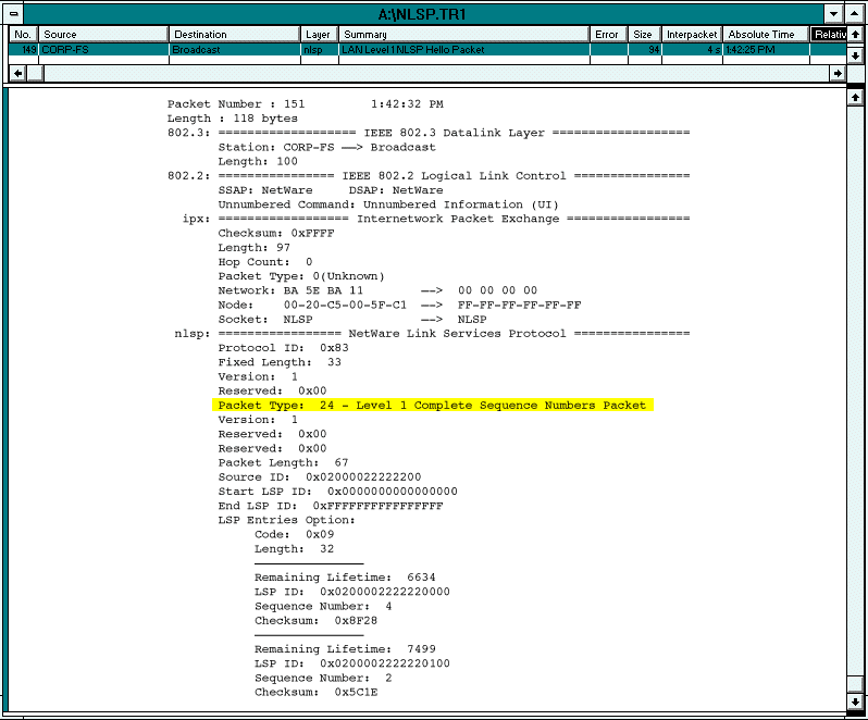
A CSNP lists the LSP ID number of every LSP ID entry in the designatedrouter's link state database. A CSNP also includes the sequence numbersand checksum values associated with the LSP ID number. (See Figure 1.)
Figure 1: This CSNP indicates that the link state database contains two LSP ID entries.

In addition, a CSNP includes aremaining lifetime, or time-to-live,field for each LSP ID entry. This field indicates when the NLSP device thatis associated with each LSP ID entry is expected to transmit the next periodicLSP packet.
Each NLSP device compares the CSNP to the device's link state databaseto see if there are any inconsistencies. If an NLSP device finds inconsistencies,the device takes one of the following actions, depending on if the designatedrouter (the sender) has up-to-date information or if the NLSP device (thereceiver) has up-to-date information:
The Designated Router Has Up-to-Date Information
If the designated router has up-to-date information, the receiving NLSP device transmits a Partial Sequence Number Packet (PSNP) to the designated router. This PSNP contains the LSP ID number identifying the LSP ID entry that the NLSP device must update in its link state database.
For example, suppose that you added the MPR1 router to a network on which the CORP-FS router were already running. The MPR1 router would obviously not have all of the information about the network that the CORP-FS router has.
After receiving a CSNP from the CORP-FS router (see Figure 1), the MPR1 router would generate a PSNP (see Figure 2), requesting more information about the two LSP ID entries in the CSNP. To indicate that the MPR1 router's information about these LSP ID entries is outdated or nonexistent, the MPR1 router would set the sequence numbers for the entries to 0. After receiving the PSNP, the CORP-FS router would transmit an LSP packet containing the requested information to the MPR1 router.
Figure 2: The MPR1 router sends a PSNP, requesting information about the LSP ID entries.

The Receiving NLSP Device Has Up-to-Date Information
If the receiving NLSP device has up-to-date information, this device does not transmit a PSNP. Instead, the receiving NLSP device transmits an LSP packet that contains the latest information (and a higher sequence number).
In addition to the designated router, all of the other NLSP devices on the network receive this LSP packet, ensuring that all NLSP devices have accurate information about the network. After receiving the LSP packet, the designated router updates its link state database and includes the new information in the next CSNP transmitted.
RECEIVING DUPLICATE INFORMATION
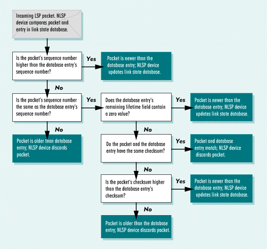
In most cases, the sequence number clearly identifies if the incomingLSP packet or the link state database has up-to-date information. Occasionally,however, an NLSP device may receive an incoming LSP packet that has thesame LSP ID number and the same sequence number as an existing LSP ID entryin the link state database. In this case, the NLSP device examines two otherfields contained in an LSP packet: the remaining lifetime field and thechecksum field. Using these two fields, the NLSP device completes the processoutlined in Figure 3 to determine if the incoming LSP packet or the existing LSP ID entry in the link state database has up-to-dateinformation.
Figure 3: The process of evaluating an LSP packet

Remaining Lifetime Field
After an NLSP device determines that the LSP packet and the correspondingLSP ID entry in the link state database have the same sequence number, thedevice examines the remaining lifetime field. Because an NLSP device transmitsan LSP packet approximately every two hours, each LSP packet includes aremaining lifetime field that indicates how long a receiving NLSP deviceshould retain the information in the LSP packet. This aging mechanism ensuresthat NLSP devices purge information from the link state database when thisinformation becomes outdated. The remaining lifetime is expressed in seconds.
The designated router includes the LSP ID entry's remaining lifetimevalue in the CSNP. For example, Figure 1 indicates that LSP ID 0x02-00-00-22-22-22-00-00 has a remaining lifetime of 6,634seconds.
You can observe how remaining lifetime values decrease by examining CSNPsthat are transmitted on the network.
After an LSP packet expires (the remaining lifetime of the LSP packetreaches zero), an NLSP device performs the following tasks:
The NLSP device retains only the LSP packet header in the link state database, indicating that the remaining lifetime is zero.
The NLSP device updates the LSP packet length and checksum fields to reflect the size of the LSP packet header (the only information retained in the link state database). The NLSP device then calculates the checksum of the LSP packet header.
The NLSP device records the time at which the remaining lifetime value became zero.
After the remaining lifetime value becomes zero, the NLSP device uses thezeroAgeLifetimeparameter to determine how long this device should keep the LSP packet header in memory. After the zeroAgeLifetime expires (the default value of this parameter is 60 seconds), the NLSP device purges the LSP packet header from the link state database.
FLOODING LSP PACKETS
As explained in the last issue ofNetWare Connection, when anNLSP device transmits an LSP packet, the LSP packet is"flooded"throughout the network. Typically, protocols that flood information causeproblems on networks that contain routing loops. (Arouting loopis created when networks that are connected by routers contain a circularpath.) To ensure that the network can handle flooded LSP packets, Novellengineers used a technology calledsplit horizon.
When an NLSP device receives an LSP packet, the device performs a seriesof checks to determine if the LSP packet is the proper length and to ensurethat the information in the LSP packet has not expired. This NLSP devicethen forwards the LSP packet to all attached circuits, except the circuiton which the LSP packet was received. This split horizon technology preventsan NLSP device from transmitting an LSP packet back to the circuit fromwhich the packet was received.
CHANGING NLSP PARAMETERS
You can use Novell's INETCFG utility to adjust the way that NLSP operateson a network. NLSP has two types of parameters:Global parametersaffect all NLSP devices, andper-binding parametersaffect only aparticular IPX circuit. (You define an IPX circuit each time that you bindIPX to a LAN driver on the server.)
Because NLSP has both global and per-binding parameters, you can customizehow an NLSP device operates on each of its circuits. For example, you coulduse a global parameter to specify the maximum number of path splits (forload balancing), and you could use a per-binding parameter to specify thecost of individual routes.
To define global parameters, you select the Protocols option in the INETCFGutility; to define per-binding parameters, you select the Bindings option.
Global Parameters
Hop Count Limit
Although the default maximum hop count for anNLSP device is 64, you can increase this parameter up to 127. However, ifRIP devices exist on a route, these devices allow a maximum hop count ofonly 15.
Maximum Number of Path Splits
If two or more routes have an equalcost, this parameter determines how many routes an NLSP device should considerin load balancing. The default value is 1 (no path splitting), and the rangeis 1 to 8.
LSP Size
This parameter defines the size of LSP packets in bytes.The default value is 512 bytes, and the range is 128 to 4,096 bytes.
Override NLSP System ID
The NLSP system ID number identifiesan NLSP device. This number is assigned automatically, using part of theNLSP device's internal IPX number.
The designated router uses a variation of its NLSP system ID number toassign the network a LAN ID number. As a result, you may want to manuallyassign the designated router a more distinctive NLSP system ID number. However,you should keep in mind that the NLSP system ID number must be unique onthe entire network.
NLSP Convergence Rate
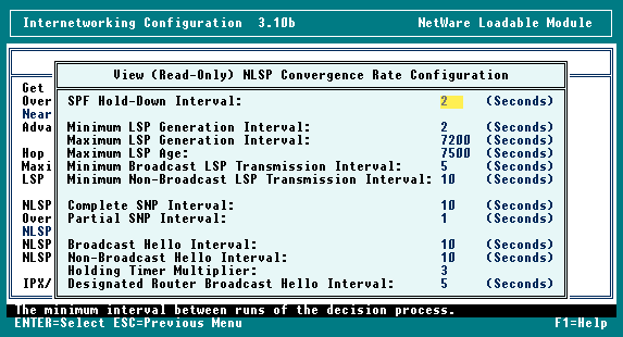
This parameter determines how fast NLSPinformation is processed. You can choose one of three values: Fast, Manual,or Default. You can then use the INETCFG utility to view a read-only filethat displays the settings for the value you selected.
By selecting the Fast value, you automatically increase the rate thatnew information is propagated throughout the network. (See Figure 4.) By selecting the Manual value, you can manually configure this parameter'ssettings to customize the NLSP convergence rate. However, Novell recommendsthat you keep the Default value, since this value should meet the needsof most networks. (See Figure 5.)
Figure 4: This read-only file displays the fast convergence rate settings.

Figure 5: This read-only file displays the default convergence rate settings.

Per-Binding Parameters
NLSP State
An NLSP device has three possible states: on, off,and auto. The default value of this parameter is Auto.
On. The NLSP device absorbs (processes) and generates RIP packets on a circuit.
Off. The NLSP device does not absorb or generate RIP packets on a circuit.
Auto. If the NLSP device detects a RIP router on a circuit, this device absorbs and generates RIP packets. Otherwise, the NLSP device does not absorb or generate RIP packets on a circuit.
Media Access Control (MAC) Channel
This parameter allows youto specify that an NLSP device sends LSP packets to the broadcast address(0xFF-FF-FF-FF-FF-FF) or to an NLSP multicast address. The following areNLSP multicast addresses:
 IEEE 802.3 0x09-00-1B-FF-FF-FF


  IEEE 802.5 0xC0-00-10-00-00-00


  FDDI 0X09-00-1B-FF-FF-FF
Maximum Transmission Unit (MTU) Override
This parameter overridesthe maximum packet size of a network interface board. The default valueis 0, which means that you do not want to override the maximum packet size.You must specify a value between 576 and 65,535 bytes to override the maximumpacket size.
You would adjust this parameter if the network included a bridge or anothernetwork device that accepts only certain packet sizes. You would also adjustthis parameter if you wanted NLSP devices to send smaller packets acrossa WAN link.
Priority
This parameter determines the priority number of anNLSP device. The priority number is used to determine which NLSP deviceis the designated router. The default value is 44, and the range is 0 to127. You can increase this value to force a particular NLSP device to becomethe designated router.
Cost Override
An NLSP device uses available throughput to determinea route's cost. For example, a 10 Mbit/s Ethernet network is assigned acost of 20. You can override the cost to force an NLSP device to use a specificroute. The range for this parameter is 0 to 63.
Pace Override
The pace indicates how many routing packets canbe sent in one second from a specific port. The default value of this parameteris based on available throughput in bits per second, and the range is 1to 1,000. For example, on a 19,200 bit/s link, the following equation determinesthe pace:
paceRate = MAX [ 1, (19,200/10,000) ]
The paceRate on this link equals 1.92. The pacing on a faster network(such as a 10 Mbit/s Ethernet network) is actually 18 packets per second.A minimum gap of 1/18 second between LSP packets prevents an NLSP devicefrom overloading other devices on the network.
CONCLUSION
This article explained how an NLSP device updates its link state databaseand how you can change NLSP parameters. The third article in this serieswill explain how NLSP devices interoperate with SAP/RIP devices.
Laura Chappell researches, writes, and lectures on protocol performance,troubleshooting, and optimization. You can reach Laura at lchappell@imagitech.com.
NetWare Connection, October 1997, pp.34-39
* Originally published in Novell Connection Magazine
Disclaimer
The origin of this information may be internal or external to Novell. While Novell makes all reasonable efforts to verify this information, Novell does not make explicit or implied claims to its validity.