IP Address Configurations and Usage for the NetWare 6.5 TCP/IP Protocol Stack
Articles and Tips: article
Software Engineer
Novell, Inc.
ASrinivas@novell.com
Special thanks to B Thavamani Rajan from Novell for his assistance with this AppNote.
01 Feb 2003
This AppNote describes all the possible IPV4 address assignments and related usage information for the TCP/IP protocol stack available in the next release of NetWare 6.5 (code-named Nakoma). It also compares the address assignment schemes to be provided with what has been set forth in various RFCs.
- Introduction
- Primary IP Address Configuration
- Secondary IP Address Configuration
- Address Assignments for Grouped Interfaces
- Virtual IP Address Configuration
- Mapping to the RFCs
- Conclusion
|
Topics |
NetWare TCP/IP, IP addresses, multihoming, virtual IP addresses |
|
Products |
NetWare 6.5 (Nakoma release) |
|
Audience |
network administrators, consultants, installers |
|
Level |
intermediate |
|
Prerequisite Skills |
familiarity with NetWare and TCP/IP |
|
Operating System |
NetWare 6.5 |
|
Tools |
none |
|
Sample Code |
no |
Introduction
In a TCP/IP-based network, various IP address configurations are possible. They can be categorized as follows:
Primary IP addresses
Secondary IP addresses
Address assignments for grouped interfaces
Assigning different Network IDs
Virtual IP addresses
This AppNote describes each of the above categories of configurations and presents the rules governing their usage in a NetWare environment.
Primary IP Address Configuration
Primary IP addresses are used to create a mapping between the attached networks and the physical interfaces on a system. These network interface associations are entered into the routing tables.
Figure 1 shows an example of a routing table for a NetWare server with five primary bindings.
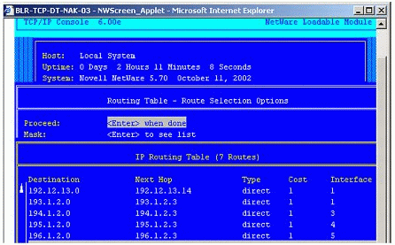
Figure 1: Primary addresses as reflected in NetWare's routing table.
The primary bindings are indicated by the entries labelled "direct" in the routing table. Each one represents a unique combination of Destination addresses and Interface numbers.
The following table summarizes the cases for the configuration and usage of class A, B, C, and zero addresses using various address mask combinations.
Note: The notation {<Network Number>,<Host Number>} is used frequently to denote a particular address. This notation is similar to the notation in section 3.2 of RFC 1122.
|
Address
|
Mask
|
Support on NetWare
|
|
{<Network Number>,<Host Number>} |
Default |
Basic configuration, which is mandatory to be supported. |
|
{<Network Number>,0} |
Default |
Explicit configuration of this address is not allowed.This is internally treated as a broadcast when specified as a destination address. |
|
{0,0} |
Default |
Explicit configuration of this address is not allowed. In NetWare it is internally maintained and used to represent an unspecified address in the connection table (see Figure 2) that its resolved to the first bound primary address in a particular network. When specified as a destination address, it is translated as a loopback address 127.0.0.1 (see Figure 3). |
|
{<Network Number>,-1} |
Default |
Explicit configuration of this address is not allowed. This is interpreted as a broadcast to be directed to the specified network. |
|
{<Network Number>, <Subnet Number>, -1 } |
Subnet |
Explicit configuration of this address is not allowed. This is interpreted as a broadcast to be directed to the specified subnet. |
|
{<Network Number>, -1, -1 } |
Subnet |
Explicit configuration of this address is not allowed. This is interpreted as a broadcast to be directed to all subnets in the specified network. |
|
{<Network Number>,<Host Number>} |
Subnet/ Supernet with contiguous bits in mask |
This configuration is allowed, but is not supported with a supernet mask routing functionality. |
|
{<Network Number>,<Host Number>} |
Subnet/ Supernet with non- contiguous bits in mask |
Non-contiguous masks are not allowed per the recommendation in Section 2.1 of RFC 950 (see Figure 4). |
The figures that follow are a series of screenshots taken on a client logged in to the Novell Portal utility running on a remote server. Such screenshots are used throughout this AppNote to illustrate various aspects of address configuration and usage.
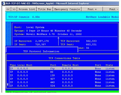
Representation of unspecified addresses in the TCP Connection Table.
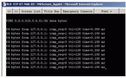
"Zero" destination being treated as loopback by NWPING.
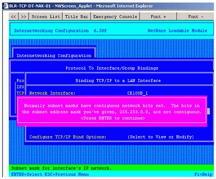
Error sent by INETCFG when trying to configure an address with the non-contiguous mask of 255.255.253.0.
Secondary IP Address Configuration
Secondary IP addresses are additional addresses that can be used in order to configure multiple logical hosts on the same interface. These addresses have several uses, which are described in this section.
Configuring Virtual IP Address
Secondary IP addresses with no ARP (Address Resolution Protocol) option are used to configure virtual IP addresses. These are used to host a virtual service such as proxy or an individual site rendered by the proxy.
Such a configuration, which resides behind a device like a load balancer switch (Web cache redirector), can enable the implementation of a load balancing policy on the switch. Once this configuration is in place, requests to the proxy are cycled across multiple proxies configured with the same virtual IP address.
In Figure 5, the Web cache redirector, cache X, and cache Y share the same virtual IP address, which is configured as non-ARPable secondary IP address when cache X and cache Y are on NetWare. (There may be one secondary IP address for each site rendered.)
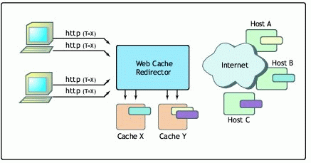
Figure 5: Use of secondary IP address in a proxy configuration.
The redirector and proxies can share the virtual IP addresses by which each site is registered with DNS (Domain Name Service). The redirector examines the destination address and port for each incoming packet. If the packet matches a virtual service, it is redirected to one of several proxies in a cluster according to some type of scheduling policy.
Constructing Static NAT Tables
Secondary IP addresses are also used to construct static NAT (Network Address Translation) tables where there is a one-on-one association between the public and private addresses.
As shown in Figure 6, the NAT router has secondary IP addresses 130.57.199.13 and 130.57.199.14, which are used in the NAT table as virtual public addresses. These addresses are substituted for the corresponding private addresses in outgoing packets originating from private hosts 10.0.0.1 and 10.0.0.3.
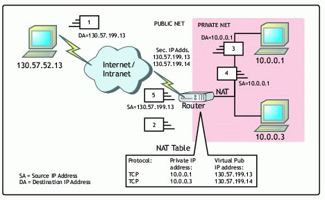
Figure 6: Use of secondary IP address in a NAT configuration.
Validation Checks
Configuration of secondary IP addresses is subject to the following validation checks:
Its network ID should match the network ID of one of the configured primary addresses. or that of the board specified.
It should not duplicate any other secondary IP address or primary address (if it is ARPable).
A maximum of 256 secondary IP addresses are allowed.
Address Assignments for Grouped Interfaces
In the current TCP/IP stack it is possible to group interfaces to support load balancing and fault tolerance (FT). With this kind of grouped assignment, it is possible to distribute incoming and outgoing traffic over the constituent boards within a group. It is also possible to fail-over the load from a faulty board to a subsequent board in the group and fail-back the load to a board that has recovered from a fault.
Two basic kinds of configurations can be used to enable these features:
Multiple NIC-Single IP Address
Multiple NIC-Multiple IP Addresses
Multiple NIC-Single IP Address Configuration
Here multiple NICs residing on the same physical network can be grouped by binding all of them to the same IP address. This configuration supports both load balancing and fault tolerance. Keep in mind that multiple interfaces bound to a single IP address are automatically grouped.
Figure 7 shows the "Group interface for FT" field set to Yes and grayed out to reflect the mandatory grouping described above.
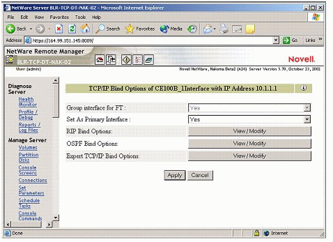
Figure 7: Option to group interfaces for Fault Tolerance under TCP/IP bind options.
Multiple NIC-Multiple IP Addresses Configuration
Multiple NICs residing on the same physical network can be grouped by binding all of them to different IP addresses of the same network and explicitly grouping them for fault tolerance by enabling the "Group for Fault Tolerance" flag in Bindings > Expert options.
The following scenarios will illustrate invalid and valid variations on this configuration.
Scenario 1. Suppose you have three interfaces and two addresses (IP1 and IP2, for example) which belong to same network. In this scenario, you attempt the following:
Configure two of the interfaces with address IP1.
Configure the third interface with address IP2 and set the "Group interface for FT" flag to Yes.
System Response 1. The configuration is saved and the two interfaces are grouped for fault tolerance (this is mandatory). However, the system sends the warning shown in Figure 8 to notify the administrator that it is adding the third binding with the "Group for FT" flag set to No.
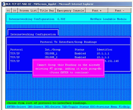
Figure 8: Warning when attempting to add binding with a different IP address (10.1.1.2) to a group of two boards (CE100B_1 and CE100B_2) with a single IP address (10.1.1.1).
Scenario 2. Suppose you have four interfaces and two IP addresses (IP1 and IP2, for example) that belong to the same network. In this scenario, you attempt the following:
Configure two of the interfaces with address IP1.
Configure the third interface with address IP2.
Configure the fourth interface with address IP2.
System Response 2. The configuration of the first two interfaces is permitted to be saved and both interfaces are grouped for fault tolerance (this is mandatory). The configuration of the third interface will be saved however the fourth configurations will not be allowed to be saved. The system sends the error message shown in Figure 9.
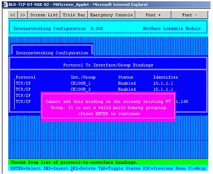
Figure 9: Error shown when trying to group two boards with IP address 10.1.1.2 when two other boards are grouped with IP address 10.1.1.1.
Scenario 3. Suppose you have four interfaces and two IP addresses (IP1 and IP2, for example) which belong to different networks. In this scenario, you attempt the following:
Configure two of the interfaces with address IP1.
Configure the third interface with address IP2.
Configure the fourth interface with address IP2.
System Response 3. The configuration for the first two interfaces is permitted to be saved and the interfaces are grouped for fault tolerance. (This is mandatory.) The configurations for the third and fourth interfaces are also permitted to be saved with no errors. This is because multiple groups can be configured on a system as long as they belong to different networks.
The resulting configuration is shown in Figure 10.
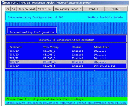
Figure 10: Multiple fault tolerance groups successfully configured on a system.
Assigning Different Network IDs
It is possible to "multihome" a host in different networks by configuring addresses with different network IDs. This can be done on a single or multiple interfaces. This configuration is done to provide forwarding, NAT, proxy and other such router-based services on NetWare.
Note: There is a known issue when assigning different network IDs in conjunction with Classless Internet Domain Routing (CIDR) masks. Once a server is configured with a supernet mask, it behaves like an end-node when IP forwarding is disabled. It continues to behave like an end-node even if the mask is changed to a non-supernet mask and the system is reinitialized. To make it work like a router, change the state of the IP packet forwarding or RIP or LAN Static Routing in INETCFG and reinitialize the system.
Virtual IP Address Configuration
A virtual IP address is an IP address bound to a virtual interface which provides fault-tolerant access to multihomed servers with multiple NICs and configured on multiple networks. The virtual IP address should belong to a network that does not match any of the "real" networks. An example is shown in Figure 11.
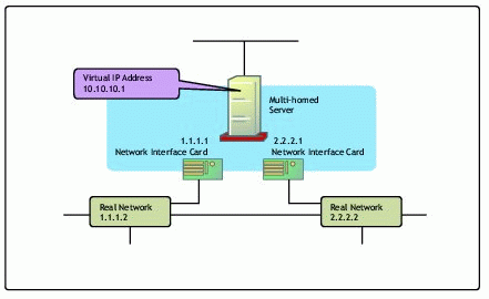
Figure 11: Example of the use of a virtual IP address.
As the virtual address is not bound to a physical interface, it is accessible all the time to the clients on the network (see Figure 12).
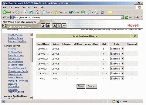
Figure 12: A virtual board (VNIC) shown in the list of configured boards.
Figure 13 depicts a virtual IP binding to a virtual NIC.
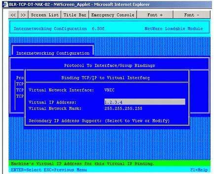
Figure 13: Binding a virtual IP address to VNIC.
In this configuration, you should be aware of the following:
A given host can reside on multiple virtual networks.
A given virtual network can spread across different hosts. In this case, the different hosts on the given virtual network should be capable of advertising their Host Routes, and the network should also be capable of handling host- based routes in preference to network routes. If this condition cannot be met, each host should reside on an exclusive virtual network (see Figure 14).
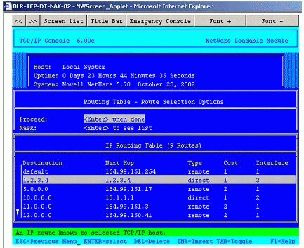
A Host Route representation of the virtual IP address bound on the system.
Clients that intend to avail themselves of fault tolerance service provided by a virtual IP address should initiate a connection with the virtual IP address.
All outbound connections (for example, TCP connections) from the server that are intended to be fault tolerant should be initiated with the virtual IP address as the Source Address. This is in contrast to the conventional method of source IP address selection where the Source Address is selected based on the outbound interface through which the packet will be routed.
All applications which, unlike routing protocols, have no preference for a specific source address for outgoing packets should preferably be made to use the virtual IP address as the Source Address. This is achieved by enabling outbound VIPA support, as shown in Figure 15.
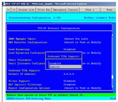
Figure 15: Enabling outbound VIPA support.
The following table describes some of the validation checks for virtual IP address configurations.
|
Scenario
|
System Response
|
|
Virtual IP address should not be loopback address or Class D address |
Should not be able to bind with 127.0.0.1 / address ranging from Class D (a multicast address 224.0.0.0 - 240.0.0.0) or Class E (241.0.0.0 - 248.0.0.0, which are reserved for future use). |
|
Configure Virtual IP address as all zeros / broadcast address |
System restricts you from configuring the address. |
|
Virtual IP address should not be same as a real IP address (for example, you bind a real IP address with 164.99.150.1 and try to bind the same IP address to a Virtual IP address) |
System restricts you from configuring the address, and vice-versa: the system should restrict you from binding to a physical board an address that is already configured on a VNIC. |
|
Virtual net cannot be the same as real net (for example, you bind a real IP address with 164.99.150.1/ff.ff.fc.0 and then a Virtual IP address with 164.99.151.1/ff.ff.fc.0) |
System restricts you from configuring the virtual address, and vice-versa: the system will not allow you to configure a real address which has same network ID as an existing virtual IP address. |
|
When your system is configured with two VNIC boards (say VNIC_1 and VNIC_2), you try to bind an IP address to VNIC_2. |
System restricts you from binding to the second bound VNIC_2 board. |
Mapping to the RFCs
This section attempts to map the NetWare TCP/IP stack's compliance to the "must" and "should" requirements set forth in the RFCs.
RFC 791, Section 2.3: "A single physical host must be able to act as if it were several distinct hosts to the extent of using several distinct internet addresses. That is, provision must be made for a host to have several physical interfaces to the network with each having several logical internet addresses."
NetWare 6.5 is fully compliant through its support for Secondary IP addresses and multihoming.
RFC 791, Section 3.2: "The local address, assigned by the local network, must allow for a single physical host to act as several distinct internet hosts. That is, there must be a mapping between internet host addresses and network/host interfaces that allows several internet addresses to correspond to one interface. It must also be allowed for a host to have several physical interfaces and to treat the datagrams from several of them as if they were all addressed to a single host."
NetWare 6.5 is fully compliant through is support for Secondary IP addresses, assignment of different network IDs on same and different interfaces, and multiple NIC-single IP address configurations.
RFC 795, Section 2.1: "Values of all zeros and all ones in the subnet field should not be assigned to actual (physical) subnets."
NetWare 6.5 is compliant (refer to the section of this AppNote on primary address configuration).
RFC 1122, Section 3.2.2.9: "Host MUST support the first, and MAY implement all three, of the following methods for determining the address mask(s)corresponding to its IP address(es): (1)static configuration information; (2) obtaining the address mask(s) dynamically as a side-effect of the system initialization process (see [INTRO:1] ); and (3) sending ICMP Address Mask Request(s) and receiving ICMP Address Mask Reply(s)."
NetWare 6.5 supports static configuration of masks. Dynamic methods of mask determination are not implemented in TCP/IP.
RFC 1122, Section 3.3.1.6: "The following information MUST be configurable: (1) IP address(es); (2) Address mask(s). A manual method of entering this configuration data MUST be provided."
NetWare 6.5 is compliant. The following are the three methods for this configuration: (1) Command line, which is volatile; (2) INETCFG, a server- based GUI utility, which is persistent; and (3) NoRM snap-in for TCP/IP configuration provided under the "Configure internetworkng" link. This is also persistent and assists in remote browser-based configuration.
RFC 1219, Section 2.0: "The subnet mask must be contiguous."
NetWare 6.5 is compliant.
Conclusion
This AppNote has discussed IP address configuration and provided usage information for the upcoming NetWare 6.5 TCP/IP stack. This information will help you plan for future TCP/IP-based network configurations.
* Originally published in Novell AppNotes
Disclaimer
The origin of this information may be internal or external to Novell. While Novell makes all reasonable efforts to verify this information, Novell does not make explicit or implied claims to its validity.