Comparing Novell's IPX-to-IP Connectivity Solutions: IP Tunneling, NetWare/IP, and IP Relay
Articles and Tips: article
Senior Research Engineer
Systems Research Department
01 Sep 1995
Novell has introduced several different solutions to interconnect IPX and TCP/IP networks. IP Tunneling was introduced as part of NetWare 3.11 and has been included in all subsequent versions of the NetWare operating system. From this basic IP-to-IPX tunneling solution, Novell has developed more efficient and sophisticated products: NetWare/IP (versions 1.1 and 2.1) and IP Relay, found in the NetWare MultiProtocol Router (MPR) version 2.0 and higher. This AppNote compares these three solutions, providing an architectural overview and discussion of the advantages of each one. It give recommendations for configuring and implementing these products effectively.
RELATED APPNOTES Apr 95 "Using NetWare/IP Over Satellite Networks"
Introduction
Several years ago, Novell recognized a growing need for customers to be able to interconnect their NetWare servers and LANs running the IPX protocol with the TCP/IP networking architecture. To support this configuration, Novell has introduced several different solutions over the years. The first offering, called IP Tunneling, was introduced as part of NetWare 3.11 and has been included in all subsequent versions of the NetWare operating system. In 1993, NetWare/IP was introduced as an add-on product for NetWare 3 and NetWare 4. A third solution is IP Relay, which is included in the NetWare MultiProtocol Router (MPR) version 2.0 and higher.
To help customers understand these products, this Application Note discusses the architectural design of each one, identifying the similarities and differences between them. It also provides recommendations for implementing and configuring them most effectively.
Background
To understand the issues discussed in this AppNote, it is helpful to have some background information on the challenges involved in integrating different networking environments.
Administration. When developing any new technology, a key architectural requirement is to simplify its deployment and management compared to existing technologies. In deploying and maintaining a network, one of the more complicated and maintenance-intensive tasks is managing network address tables. These tables contain a name and an address for each network entity, which serve as the means of identifying devices, services, and users on the network. To prevent address conflicts, each name and address in the table must be a unique pair. To reduce the possibility of address conflicts and potentially simplify network management, network address tables are usually managed by a central resource.
TCP/IP networks require manual administration in the form of installing and maintaining UNIX-based computers to act as Domain Name Servers. IP does not perform regular broadcasts that identify network services. An administrator must manually assign IP addresses to all hosts and router ports, and ensure that no duplicate IP addresses exist. A separate computer can be set up as a server to dynamically allocate IP addresses from a pool of available address ranges, but this also requires the services of an IP administration staff to install and maintain.
In NetWare, information about available services and routes is propagated dynamically to eliminate the administrative burden of managing static address tables. Updates are broadcast using NetWare's Routing Information Protocol (RIP) and Service Advertising Protocol (SAP) at preconfigured intervals (every 60 seconds). Each server/router on the network receives these RIP and SAP broadcasts and updates its internal tables accordingly. This dynamic updating process simplifies both the installation of new devices and the interconnection of multiple network segments.
However, dynamic updates can affect overall system performance in larger networks. As the number of advertising devices and network segments increases, the amount of traffic generated to update the network address tables increases exponentially. Without careful planning, update traffic can become excessive, resulting in poor network performance. In cases where networks are connected via non-LAN links (X.25, 56Kbps, T1, satellite, dial-up, and so on), update traffic can consume nearly all the available bandwidth, leaving little room for user data.
Novell's Approach. Normally, NetWare uses IPX to propagate RIP and SAP update information. With IP Tunneling, IPX packets are simply encapsulated inside of IP frames. This does nothing to alleviate the problem of excessive update traffic on larger networks, since IPX RIP and SAP broadcasts are also encapsulated and transmitted across the IP tunnel.
In NetWare/IP and IP Relay, Novell's approach is to use a combination of native IPX and IP, tunneled packets, and protocol "spoofing" to achieve better integration between NetWare and TCP/IP. By combining the features and administration of TCP/IP and Novell's IPX, NetWare/IP and IP Relay can take advantage of NetWare's dynamic update feature without incurring the normal overhead associated with RIP and SAP traffic. This is particularly significant in a distributed network that uses low-speed, low-bandwidth links.
Human Interface. Another key factor, though a non-technical one, is the human interface. Users and administrators in both NetWare and UNIX environments expect new management utilities to be consistent with those they are accustomed to using. Due to the technical differences between operating systems and the varying experience of the users of these systems, integrating the human interface can be very difficult.
Novell attempts to build utilities for both users and administrators that behave as expected. The goal is to present new, nontraditional aspects in a manner that is consistent with the user's native environment. Cross-platform products designed to integrate NetWare and UNIX from either perspective are available from several groups at Novell.
IP Tunneling
Starting with NetWare 3.11, Novell introduced a feature called IP Tunneling into the NetWare environment. IP Tunneling is implemented as a NetWare Loadable Module (IPTUNNEL.NLM) that is loaded on file servers connected in point-to-point fashion across an IP-only internetwork. In this configuration, IP is used to interconnect LANs (typically over a remote link), while clients continue to use IPX to talk to the servers.
The IPTUNNEL driver on the servers simply encapsulates IPX/NCP packets inside an IP frame, adding a User Datagram Protocol (UDP) header, an IP header, and an IP checksum field for a cyclic redundancy check or CRC (see Figure 1).
Figure 1: In IP Tunneling, IPX/NCP data is encapsulated inside an IP frame before being sent across an IP connection.

This solution passes all packets normally carried on an IPX network. Thus clients can communicate using native IPX/NCP to either a local or remote IPTUNNEL server. In this way, IP Tunneling provides IP interconnectivity with a minimal impact on network administrators and users.
IP Tunneling Architecture
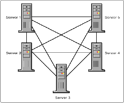
IP Tunneling is based on a broadcast LAN architecture. This means all routes are broadcast to all routers on the network (see Figure 2).
Figure 2: IP Tunneling architecture.
To minimize support requirements, network administrators can designate a few servers to carry the IP encapsulated traffic. To do this, all end-point servers must be assigned a unique IP address and each server must specify the destination address of the remote server. Tunneling between servers allows all users complete access without requiring any modifications to the client workstations.
Though easy to configure, IP tunneling passes all IPX traffic, including SAP and RIP traffic. Caution should be used when connecting sites that have many advertising devices over a limited-bandwidth link (a typical implementation of IP Tunneling). Broadcast packets can easily consume a disproportionate amount of the bandwidth, leaving little bandwidth for application data and resulting in poor response time for users.
RIP Traffic Calculation
To determine the number of RIP packets generated by IP Tunneling, consider the number of RIP messages generated by the full mesh network configuration shown in Figure 2. Though this design may not be implemented in practice, it provides an instructional model for calculating RIP traffic. (This calculation does not include any SAP traffic.)
The following chart tabulates the total number of RIP packets passed between the five IPTUNNEL servers.
|
RIP Packet
|
RIP Packet
|
RIP Packet
|
RIP Packet
|
RIP Packet
|
|
|
Server 1 |
Internal IPX to FFFF |
Tells Server 2 about 3,4,5 |
Tells Server 3 about 2,4,5 |
Tells Server 4about 2,3,5 |
Tells Server 5about 2,3,4 |
|
Server 2 |
Internal IPX to FFFF |
Tells Server 1 about 3,4,5 |
Tells Server 3 about 1,4,5 |
Tells Server 4about 1,3,5 |
Tells Server 5about 1,3,4 |
|
Server 3 |
Internal IPX to FFFF |
Tells Server 2about 1,4,5 |
Tells Server 1about 2,4,5 |
Tells Server 4about 2,1,5 |
Tells Server 5about 2,1,4 |
|
Server 4 |
Internal IPX to FFFF |
Tells Server 2about 3,1,5 |
Tells Server 3about 2,1,5 |
Tells Server 1about 2,3,5 |
Tells Server 5about 2,3,1 |
|
Server 5 |
Internal IPX to FFFF |
Tells Server 2about 3,4,1 |
Tells Server 3about 2,4,1 |
Tells Server 4about 2,3,1 |
Tells Server 1about 2,3,4 |
|
Total RIP Packets |
5 packets |
5 packets |
5 packets |
5 packets |
5 packets |
If the RIP information is too large to fit into one packet, multiple packets are created. The formula for the maximum RIP packet size is as follows: MaxRipPacketSize = (MaxRipEntries x RipEntrySize)+32 = 432
The size of each RIP entry is 8 bytes, and the maximum number of RIP entries per packet is 50. The maximum RIP packet size is therefore 432 bytes (400 bytes of data plus a 32-byte header).
In our example above, 25 RIP packets are created. Since the number of entries does not exceed the maximum of 50 per packet, the total number of RIP packets sent per minute is 25. To figure the size of each packet, take the number of servers minus 1 (nB 1 = 4), and multiply that by 8 bytes per entry. For our example, this equals 32 bytes of RIP data. Adding the 32-byte header yields a total of 64 bytes per RIP packet. For five servers broadcasting 25 RIP packets once a minute, approximately 1600 bytes (25 x 64)or 12,800 bits of RIP data is transmitted every minute. If the servers were connected over a 9.6 Kbps remote link, this would take 1.3 seconds.
NetWare/IP
NetWare/IP is a hybrid product that uses both encapsulation and standard IP packets. It is designed specifically to integrate NetWare services into TCP/IP environments. NetWare/IP's design allows existing NetWare users to continue working in their same environment, using IP (encapsulated IPX) as the underlying communications protocol.
NetWare/IP adds new design and architectural capabilities for deploying and supporting NetWare in local and wide area networks. NetWare/IP consists of several independent, cooperating client and server components:
NetWare/IP client
NetWare 3.1x or 4.x servers
Domain Name System (DNS) servers
Domain SAP Servers (DSS)
The NetWare/IP client software consists of a TCP/IP stack (TCPIP.EXE), a module called NWIP.EXE, and either the NetWare shell (NETX.EXE) or the NetWare DOS Requester (VLMs).
|
Note: Support for Novell's new 32-bit NIOS client is currently in testing and will be available when version 1.0 is released. |
The NetWare/IP v1.1 server runs on either NetWare 3.1x or 4.x. NetWare/IP v2.1 runs only on NetWare 4.x servers. NetWare applications that previously used IPX can run on a NetWare server using IP.
The Domain Name System (DNS) server is a distributed look-up service that allows system administrators to centralize host name-to-IP address information. It provides a flexible way for NetWare/IP client and servers to locate Domain SAP Servers.
Domain SAP Servers (DSS) maintain a database used to store and disseminate IPX SAP information to NetWare/IP clients and servers.
NetWare/IP Client Architecture
To understand the architecture of the NetWare/IP client, we can compare it to the traditional NetWare client architecture represented in Figure 3.
Figure 3: The standard NetWare client architecture.
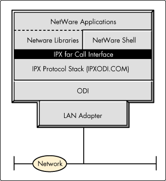
The bottom or physical layer supports standard network interface cards. ODI drivers, or MLIDs, reside at the next higher layer. The ODI driver links the LAN adapter below it to the protocol stack above it.
The protocol stack (IPXODI.COM) is responsible for the end-to-end transport of data between systems. It exports an Application Binary Interface (ABI) called the IPX Far Call Interface that is backwards compatible with early versions of IPX.
The NetWare shell, libraries, and applications are at the highest layer in the NetWare Client architecture. They use the protocol stack (IPXODI) layer to transmit data by making a function calls to IPXODI.COM using the IPX Far Call Interface.
The key to enabling all existing and future NetWare applications to run over TCP/IP lies in making the IPX Far Call Interface available to applications over TCP/IP instead of IPX. Figure 4 shows how this is accomplished in the NetWare/IP client software.
Figure 4: The NetWare/IP client architecture.
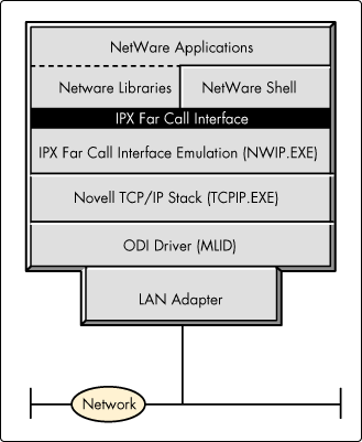
The NetWare/IP client architecture is identical to the traditional NetWare client architecture at the hardware, ODI, and application layers. It is different at the transport layer. Instead of using IPX to transmit information, the NetWare/IP client utilizes the User Datagram Protocol (UDP) in the Novell TCP/IP protocol stack (TCPIP.EXE). This TCPIP.EXE is the same protocol stack used in Novell's LAN Workplace for DOS and LAN Workplace for Windows products.
Many people have wondered why the NetWare client does not run natively over TCP/IP. Porting the NetWare client software to run over TCP/IP is not as simple as replacing IPXODI.COM with TCPIP.EXE. The reason is that the ABI that applications use to call into TCPIP.EXE is different from the IPX Far Call Interface used by NetWare applications that call IPXODI.COM. To address this problem, NWIP.EXE sits above TCPIP.EXE and exports the IPX Far Call Interface to NetWare applications, libraries and shells above it, while making the appropriate calls to TCPIP.EXE below.
This client architecture allows current and future NetWare applications using the IPX Far Call Interface ABI to run unmodified with TCP/IP. In fact, either NETX.EXE or the VLMs may be used at the client. However, there are limitations on IPX-based NetBIOS and other applications that depend on IPX broadcast mechanisms. These other applications are limited to their local subnet because IP routers do not forward non-direct UDP broadcasts to other subnets.
NetWare/IP Server Architecture
The NetWare/IP server platform is either NetWare 3.1x or 4.x. As noted previously, NetWare/IP 2.1 runs only on the NetWare 4.x platform. Servers can be either local or remote to the client.
Domain Name System (DNS). NetWare/IP includes an implementation of the Domain Name System (DNS) server, a distributed look-up service widely used in UNIX and TCP/IP environments to centralize host name-to-IP address information.
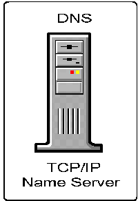
NetWare/IP, like most products in the TCP/IP arena, supports mnemonic naming of hosts. The table used for this lies off the root in a file called sys:etc/hosts. This file simply lists each IP address and the name associated with it. For example:
45.12.4.2       salmon
45.15.54.76     lobster
45.87.34.12     kipper
With this host database in place, the mnemonic names can be used in place of TCP/IP addresses when using client utilities to communicate with remote devices. For example, a client can use "telnet lobster" instead of "telnet 45.15.54.76" to engage in communication with that remote host.
As convenient as this mnemonic naming system is, manually updating each host database in a large network would be an arduous, time-consuming task. DNS overcomes this obstacle by centrally storing and maintaining tables that map readable host names to IP addresses. This information can be queried by other TCP/IP nodes on the network to identify IP addresses and their corresponding nodes.
In existing TCP/IP internetworks, DNS uses domains to simplify and organize the various network sections that are managed by different system administrators. These DNS domains are organized into a hierarchical tree structure, with subdomains branching off a single root. Each domain is administered separately, eliminating the need for centralized allocation of IP addresses and host names. A domain can be divided into multiple subdomains.
A NetWare/IP network usually consists of one NetWare/IP domain, but if necessary it can be partitioned into multiple NetWare/IP domains. A NetWare/IP domain is defined by creating a DNS subdomain under an existing DNS domain. The NetWare/IP domain does not have any subdomains under it.
|
Note: DNS domains and NetWare/IP domains are not one and thesame. A NetWare/IP domain is a terminating leaf node of DNS thatconsists of a logical grouping of NetWare/IP clients, serversand DSS servers. NetWare/IP domains are subdomains of a DNS domain. |
After the NetWare/IP domain name is created in DNS, all NetWare/IP components (client, server and DSS) which are members of that domain must be configured with the NetWare/IP domain name (for example, nwip.utah.novell.com).
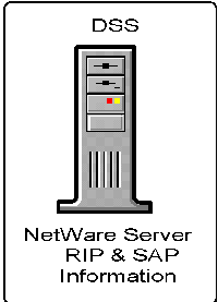
Domain SAP Server (DSS). Another major component of the NetWare/IP architecture is the Domain SAP Server (DSS). The DSS holds one logical database that stores and disseminates IPX SAP information to NetWare/IP servers. Each DSS maintains SAP information for a single NetWare/IP domain. There is only one primary DSS within each NetWare/IP domain, and optionally one or more secondary DSS databases.
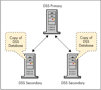
The DSS database can and should be physically replicated on multiple servers for reliability, fault tolerance, and better performance across slow WAN links (see Figure 6). Since NetWare/IP nodes contact the DSS that is nearest to them, performance can be improved by placing secondary DSS servers on each subnetwork connected by the WAN.
Figure 6: Replicating the DSS on secondary servers.
Updating the DSS with SAP Information
NetWare services, such as a file, print, and directory services, advertise themselves via the Service Advertising Protocol (SAP). Every 60 seconds these services broadcast a SAP packet that lists their name, service type, and address information. The packets are sent out on every network interface that IPX is bound to on the NetWare server that supports these services. This is how NetWare 3.1x servers and clients discover the location of services on an IPX internetwork.
When a NetWare server boots, it alerts the network to its existence by sending a SAP broadcast throughout the rest of the network. Similarly, when a NetWare/IP server boots, it advertises itself to the rest of the network by sending a SAP record directly to its nearest DSS using the User Datagram Protocol (UDP).
Subsequently, the NetWare/IP server refreshes its SAP information every five minutes (configurable) by resending it to the DSS. This refresh is necessary because the DSS monitors when SAP records are received and discards old ones if they have not been validated within a certain time interval.
Other processes on the NetWare/IP server, such as print servers and NetWare Directory Services (NDS), advertise themselves using SAP broadcasts. These broadcast packets are also sent by the NetWare/IP server directly to the DSS using UDP. This method of direct forwarding prevents SAP packets from being sent through every network interface, thereby reducing the network traffic generated by such broadcast protocols. This makes NetWare/IP well suited for deployment in large network environments.
Updating the NetWare/IP Server with SAP Information
In a native NetWare environment, NetWare servers listen to SAP broadcasts to build their internal services tables. Because applications must be able to locate objects in the bindery (pre-NetWare 4.x), NetWare servers keep the bindery updated with the latest SAP information. With NetWare/IP, this is accomplished by periodically downloading SAP information from the DSS to server cache memory and storing it in the bindery. Like the DSS updates, this occurs every five minutes (configurable).
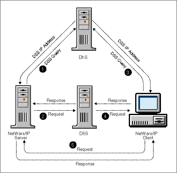
Figure 7 summarizes the relationship between the NetWare/IP client and server components.
Figure 7: Relationship between NetWare/IP components.
IP Relay
IP Relay is a new product that ships with Novell's MultiProtocol Router 2.x and 3.0 software. This product is similar to IP Tunneling in that it uses an encapsulation method. However, because it is a point-to-point WAN architecture, IP Relay scales better. Its architecture also simplifies administration and installation of remote destination devices.
IP Relay Architecture
IP Relay uses encapsulation, but its point-to-point WAN design makes it much easier to deploy and administer than IP Tunneling. To understand how IP Relay works, we'll use a telephone system analogy. Although placing and receiving a phone call does not happen in the same technical manner, the similarities are close enough to help define an IP Relay network. In this simple analogy, no consideration is given to redundancy, fault tolerance, alternate paths, and so on - all of which must be considered when working with IP Relay.
To make a phone call, you pick up the phone (off hook), dial the number you want, and wait for the other side to answer. Once the connection is acknowledged (the receiving phone goes off hook), the communication channel is open.
Note the following points in this analogy. First, in the phone system all handsets are connected to the Central Office (CO) switch, resembling a star or hub network topology. Second, a table of phone numbers is maintained at the CO. Third, "remote" destinations are in listen mode. They can receive incoming calls, but they cannot initiate calls (see Figure 8).
Figure 8: IP Relay can be likened to the phone system.
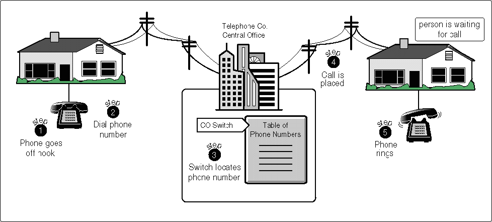
To successfully complete a call, you need to know only the phone number of the destination. The phone number from which you are calling is irrelevant. This makes it possible to place a call from any phone and always get to the same destination.
An IP Relay network is best implemented in a star or hub design with IP Relay loaded on the hub server and on the destination (remote) servers. The hub server has a table of all IP address for each destination server. The destination servers do not have the IP address for the hub server. Only the hub server knows the address of who it will call. Remote servers are in listen mode and must simply wait until the hub server attempts to open a communication channel.
At the hub server, the network administrator enters all the IP addresses from within the INETCFG utility. INETCFG then formats the information to create the appropriate IP Relay WAN call information. To open a communication session, IP Relay uses the process illustrated in Figure 9.
Figure 9: Opening a communication session with IP Relay.
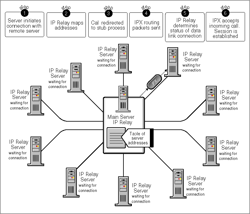
At the hub server, IPX initiates an IP connection internally through IP Relay.
IP Relay maps the connection information to the appropriate IP address.
The call request is intentionally redirected to a stub process in the same server. The stub process responds by replying that the connection is established (this is sometimes referred to as "spoofing").
At this point, no packets have left the server, and no connection is open with any of the remote servers. It is as if the phone has not yet started to ring at the destination site.
At the hub server, NetWare is told that the connection is open and IPX begins sending routing packets via IP Relay (using UDP) to the destination node. The UDP packets (containing IPX routing information) leave the hub server at this point.
At the destination node, the IP Relay server extracts the source IP address and checks to see if it currently has a Data Link connection with the hub server. If not, all packets are buffered as they come in, and IP Relay generates an incoming call and sends it to IPX.
When IPX accepts the call, the session is opened and all buffered packets are passed to IPX at the remote server.
All packets destined for the remote IP address or the IPX address are encapsulated with an IP header and checksum. All RIP and SAP packet are IP-encapsulated IPX packets.
RIP Traffic Calculation
The amount of RIP traffic generated in an IP Relay configuration can vary substantially depending on the network design. In a star or hub design, there is a linear relationship between the number of RIP packets and the number of servers (n), whereas in a full mesh design it is n2.
Using an eleven-server network as an example, below are the calculations of the amount of RIP traffic generated in a hub design and in a full mesh design with IP Relay.
IP Relay (hub design) RIP entries = (11 - 1) x 8= 80 RIP packets = 11 Bytes broadcast = 880 bytes or 7,040 bits every minute
IP Relay (full mesh design) RIP entries = (11 - 1) x 8= 80 RIP packets = 121 Bytes broadcast = 9,680 bytes or 77,440 bits every minute
IP Relay Advantages
In summary, IP Relay offers a number of advantages over IP Tunneling:
In a wide area configuration, IP Relay scales better because it is a point-to-point LAN architecture.
When properly designed, IP Relay generates substantially less RIP traffic.
Through INETCFG (a console utility that comes with MPR), the frequency of RIP and SAP packets can configured as yet another means of reducing traffic.
The architecture simplifies administration and installation of remote destination devices.
It is integrated with the WAN version of NetWareLink Services Protocol.
Recommendations
This section gives recommendations for configuring and implementing each of the three IPX-to-IP solutions most effectively.
IP Tunneling
In a wide area network configuration, IP Tunneling is appropriate for connecting a small number of servers. With a large number of servers, the amount of traffic generated by servers may become an issue, especially when bandwidth is limited.
We tested the throughput of both IP Tunneling and NetWare/IP with two servers and found no measurable difference. However, as the number of servers increases, tunnelling adds substantially more traffic.
When the connections are all at LAN speeds, the only other real concerns are ease of configuration and network management.
NetWare/IP
There are many differences between NetWare/IP and NetWare's IP Tunneling. The primary differences are:
NetWare/IP uses the DSS for lookup services
NetWare/IP has several configurable parameters to optimize RIP and SAP traffic over connections with limited bandwidth and high latency (see "UsingNetWare/IP Over Satellite Networks" in the April 1995 Novell Application Notes for details)
The scalability and efficiency of NetWare/IP make it a preferred solution to IP Tunneling. When implementing NetWare/IP, be sure to replicate the DSS on local servers. This improves response time for local users and provides redundancy to the client.
IP Relay
IP Relay is best deployed in a star or hub configuration. If IP Relay is deployed in a full mesh network, there will be no reduction in RIP traffic. A true star design, however, does not provide for redundancy or fault tolerance. Therefore, you should modify the basic configuration to provide an additional path.
IP Relay is preferred over IP Tunneling for interconnecting remote sites using an IP backbone or backhaul. When replacing IPTUNNEL connections, a new design should improve performance.
Conclusion
Novell provides three products for interconnecting IPX network segments to IP segments. Generally, IP Tunneling is the least preferred solution, although in certain instances it is adequate. NetWare/IP and IP Relay are much more flexible and scalable and should be used whenever feasible, especially for larger networks.
* Originally published in Novell AppNotes
Disclaimer
The origin of this information may be internal or external to Novell. While Novell makes all reasonable efforts to verify this information, Novell does not make explicit or implied claims to its validity.