The Benefits of Using Intelligent LAN Channel Processing in NetWare Servers
Articles and Tips: article
Senior Research Engineer
Novell Systems Research
01 May 1995
The NetWare LAN channel is often the focus in efforts to optimize the performance of NetWare servers. This AppNote examines the architectural options found in LAN adapter designs as they relate to NetWare servers. It discusses several important lessons learned during the development of the NE3200. It also measures the performance of a new Fast Ethernet LAN adapter, co-developed with Intel, that produces dramatic improvements in server bandwidth.
- Introduction
- LAN Channel Processing
- Lessons Learned While Developing the NE3200
- Performance Gains with Fast Ethernet Server Adapters
- Conclusion
- How We Tested the Server LAN Channel
Introduction
Novell has considered a variety of solutions to improve the bandwidth of the NetWare LAN channel without impacting the server's CPU utilization. In the process we've found that adding intelligence to the LAN adapter by incorporating a microprocessor in the design produces significant benefits, including:
Dramatic increases in server LAN channel bandwidth
Decreased LAN channel-related CPU utilization
Creation of an independent I/O subsystem that off-loads the LAN channel processing to an independent processor
This AppNote explains the benefits of intelligent LAN adapters specifically designed for NetWare servers. We'll look at several important lessons learned during Novell's development of the NE3200 server adapter. We'll also see the application of that experience in the new Fast Ethernet server adapter co-developed with Intel.
Client vs. Server LAN Channels
The client and server LAN channels are very different. A client's use of its LAN adapter is the result of a single user running a limited number of applications, carrying on a single conversation with the server. Traditional client adapters are designed without an on-board microprocessor (intelligence) because they can rely on the client's CPU to process foreground activities that require network I/O. The phrase "dumb LAN adapter" isn't a negative description but simply describes the lack of a microprocessor on the adapter. Client systems running personal productivity as well as high-bandwidth applications achieve high-speed network throughput with dumb LAN adapters.
Server LAN channel activity, on the other hand, is the result of simultaneous conversations with tens, hundreds, even thousands of clients. A server can't devote its CPU resources to the LAN channel without hurting the performance of other operations.
The server's massive bandwidth requirements, combined with the high value placed on the server's CPU resources, suggest that server adapters should be designed differently than client adapters. These differences also suggest that high-performance client adapters may not perform well in NetWare servers. Conversely, high-performance server adapters may not perform well as client adapters.
If you take the server's bandwidth requirements seriously, your ideal server adapter would be an independent I/O subsystem. Borrowed from mainframe terminology, an I/O subsystem is a processor that off-loads work from the primary CPU. An I/O subsystem in the LAN channel would perform all of the LAN channel operations independent of the server CPU. This would free the server's CPU to focus on processing NetWare Core Protocol (NCP) requests and running server applications.
LAN Channel Processing
Before we explore two intelligent server LAN adapter designs, it's important to characterize the work being done in the LAN channel and look at the different ways a server adapter might be designed to off-load the work from the server's CPU.
The LAN channel handles all inbound and outbound packets made up of client request-response traffic as well as the overhead produced by server and management protocols. The LAN channel workload produced by these packets can be categorized into three areas:
Packet receive and transmit operations
Packet processing
Packet data transfer
Packet Receive and Transmit Operations
All LAN adapters have a component called a LAN controller. This silicon component, produced by companies such as AMD, Intel, National Semiconductor, and SMC, handles the physical layer receive and transmit operations for the adapter.
The host CPU is not involved in the actual physical layer receive and transmit processes. However, the CPU is usually notified of the event through interrupts. The interrupt process produces some unnecessary overhead that we'll examine later in the article.
Packet Processing
Event Control Blocks (ECBs) are the data structures used to transfer packets between the adapter and server memory. During packet reception, LAN adapters and drivers must fill in six fields in the Receive ECB (RCB):
|
ProtocolID |
the IDof the protocol |
|
BoardNumber |
the logicaladapter number from the internal configuration table |
|
ImmediateAddress |
the sourceor destination address in the packet header |
|
Driver WorkSpace |
driver-dependentwork space |
|
PacketLength |
the lengthof the packet data |
|
FragmentLength1 |
the length of the first fragment buffer |
During each packet reception, a dumb LAN adapter relies on the host CPU to fill in these fields from the information it retrieves from the packet header.
During packet transmission, these fields are already filled in by the upper protocol layers. But the media headers have to be built from the Transmit ECB (TCB) information, which is extensive.
Packet Data Transfer
The data contained in each packet received by the adapter must be transferred to operating system memory before it can be serviced. Conversely, data for each packet transmitted by the server must first be transferred to the adapter from operating system memory. If left to the host CPU, these processes can have a significant effect on server performance.
There are four basic data transfer methods available to LAN adapter designers:
Programmed I/O (PIO)
Shared Memory
Direct Memory Access (DMA)
Bus Mastering
|
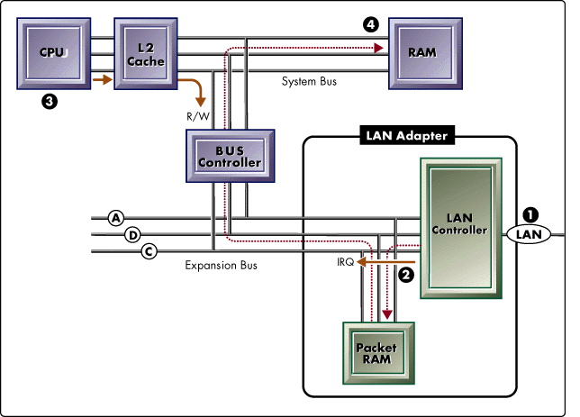
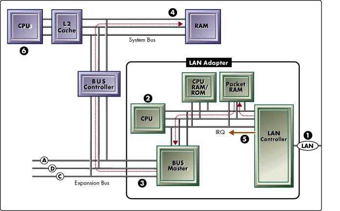
Understanding the System Diagrams Figures 1 through 5 are basic systemdiagrams that can represent a server or client PC. The systemincludes a CPU with its Level 2 Cache and RAM each attached tothe system bus. The bus controller connects the system bus tothe expansion bus where a LAN adapter is inserted into a bus slot.A, D, and C represent Address, Data, and Control lines in thesystem and expansion busses. |
PIO and Shared Memory. If the adapter is designed to use PIO (Figure 1) or Shared Memory (Figure 2) to move packets to and from host memory, the CPU is doing all the work. In these cases, the CPU calls the adapter's Interrupt Service Routine (ISR) in the adapter driver and performs the necessary packet processing and data transfer.
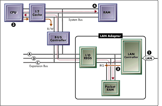
Figure 1: Programmed I/O (PIO) LAN adapter.
Programmed I/O (PIO) refers to a LAN driver's use of the IN and OUT CPU instructions. Both instructions allow the LAN driver to address I/O ports on the LAN adapter and transfer data between those ports and memory. PIO LAN drivers rely completely on the host CPU to execute the LAN driver's data transfer routines.
Figure 1 shows (1) a packet reception through the LAN controller into packet RAM, (2) an interrupt to schedule the LAN driver ISR, (3) the ISR issuing an I/O port read-write request on the control bus, (4) data moving from adapter packet RAM through an adapter I/O port into system RAM via the CPU.
These CPU-intensive processes are appropriate in client systems because the client is likely waiting on the data and has extra CPU cycles to use for this processing. But if PIO or Shared Memory methods are used in a NetWare server, the adapter is using precious CPU cycles that would be better devoted to more important, core processing tasks.
Figure 2: Shared Memory LAN Adapter.

Shared Memory refers to a LAN driver's use of the MOV CPU instruction. MOV allows the LAN driver to directly address host and adapter memory and transfer data between the two locations. Shared Memory LAN adapters rely completely on the host CPU to execute the LAN driver's data transfer routines.
Figure 2 shows (1) a packet reception through the LAN controller into packet RAM, (2) an interrupt to schedule the LAN driver ISR, (3) the ISR issuing a memory read-write request on the control bus, (4) data moving from adapter packet RAM to system RAM under control of the CPU.
Direct Memory Access 8237 Direct Memory Access (DMA) controllers are rarely used in LAN adapters because of several shortcomings, particularly a slow internal clock (4.77MHz) in the controller. DMA adapters use a DMA controller on the system board or they can build an on-board DMA controller into the adapter design.
One such adapter used an on-board 8237 DMA controller in cascade mode, allowing the adapter to arbitrate for control of the bus. The adapter then used DMA block transfers to move data between adapter and server memory. Although its performance was sufficient for clients the adapter produced disappointing results in server configurations because of 8237 DMA controller's slow transfer rate.
Figure 3: Direct Memory Access (DMA) LAN Adapter.
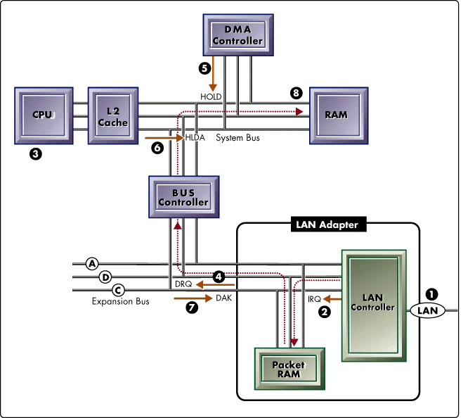
Direct Memory Access (DMA) is a data transfer method that uses an 8237 DMA controller originally built into the IBM PC motherboard. This controller allows an I/O device such as a LAN adapter to transfer large blocks of data to and from system memory without the assistance of the CPU.
Figure 3 shows (1) a packet reception through the LAN controller into packet RAM, (2) an interrupt to schedule the LAN driver ISR, (3) the ISR programs the DMA controller via the CPU using PIO, (4) the ISR issues a DMA request to the DMA controller, (5) the DMA controller issues a bus HOLD request to the CPU, (6) the CPU issues a hold acknowledge to the DMA controller, (7) the DMA controller issues a DMA acknowledge to the LAN adapter, and (8) the data transfer takes place.
Bus Mastering. With bus mastering, an adapter can perform bus operations independent of the host CPU. Bus mastering adapters have the ability to arbitrate for control of the host bus (MCA, EISA, or PCI). Once they have control of the bus, bus masters can address both adapter and server memory and transfer data between the two locations independent of the host CPU.
There are two kinds of bus master LAN adapters: dumb (Figure 4) and intelligent (Figure 5).
Figure 4: Dumb Bus Master LAN adapter.
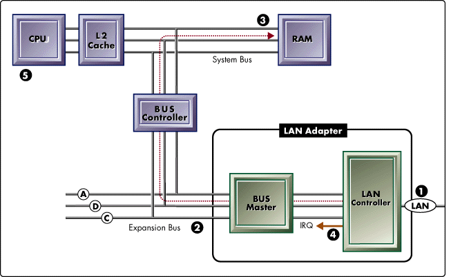
Bus mastering allows a dumb LAN adapter to move packet data to and from system memory without the involvement of the host CPU. Most dumb bus masters don't have packet RAM on the adapter because of their ability to move incoming and outgoing data so quickly.
Figure 4 shows (1) a packet reception through the LAN controller, (2) the LAN adapter arbitrates for control of the bus, (3) the adapter bursts the data to system RAM, (4) an interrupt is fired to schedule the LAN driver ISR, (5) the ISR performs packet processing and coordinates the receive or transmit operation with upper-layer protocols.
Figure 5: Intelligent Bus Master LAN adapter.
An intelligent bus master adapter incorporates a CPU into the adapter design. The adapter shown in Figure 5 includes a CPU, RAM and ROM for LAN driver and adapter firmware, and a large packet RAM. This design creates an I/O subsystem that can operate independently of the system CPU and off-load the majority of LAN channel processing.
Figure 5 shows (1) a packet reception through the LAN controller, (2) the on-board CPU handles all packet processing, (3) the LAN adapter arbitrates for control of the bus, (4) the adapter bursts the data to system RAM, (5) an interrupt is fired to schedule the LAN driver ISR, (6) the ISR coordinates the receive or transmit operation with upper-layer protocols.
Now that we've seen what processing is involved in the LAN channel and what architectural options are available to the adapter manufacturer, let's take a look at some history behind the development of intelligent server LAN adapters.
Lessons Learned While Developing the NE3200
Novell began looking at the benefits of intelligent server LAN adapters in 1987 when many customers where running into the top end of Ethernet and Token-Ring performance. By 1989 Novell, in partnership with Compaq and Intel, had developed the first prototype of the NE3200. The NE3200 now serves as the reference platform for other intelligent server LAN adapters designed for NetWare servers.
During the development process, we learned a number of valuable lessons that can benefit adapter designers as well as network designers, implementers, and managers.
Design Goal
The primary goal for the NE3200 project was to off-load as much work as possible from the host CPU onto the NE3200 while maintaining high throughput. Success would be achieved by sustaining high throughput with a minimal impact on the host CPU (low CPU utilization).
Initial Design
To meet this design goal, the initial NE3200 included an on-board microprocessor, full EISA bus master capabilities, and 32KB of buffer memory. The NE3200 specifications include:
An Intel 80C186 Microprocessor with 16KB of RAM
An Intel 82586 LAN coprocessor with 32KB of packet RAM
An Intel 82355 EISA Bus Master Interface Chip(BMIC)
The on-board microprocessor handled all ECB processing while the adapter BMIC moved the ECBs to and from server memory, all with minimal involvement of the server CPU. This architecture allowed the first prototype to perform very well - with one exception: the adapter was using interrupts to signal the CPU with each packet reception and transmit.
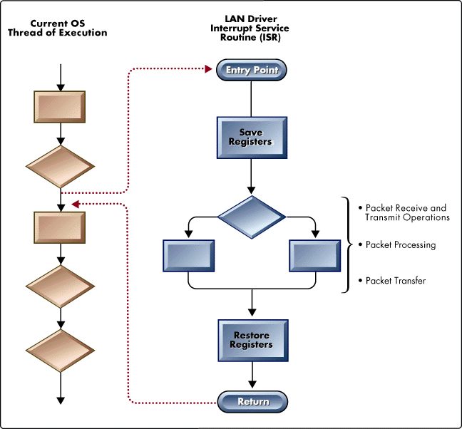
The Problem with Interrupts. Interrupts are a common method for scheduling asynchronous events in an operating system, but they can be costly, especially in a server. As shown in Figure 6, when the CPU is interrupted, the address of the Interrupt Service Routine (ISR) is placed in the CPU's instruction counter as the next instruction. In essence, the CPU leaves its current thread of execution and jumps into the ISR. The ISR then pushes all of the registers onto the stack, saving the CPU's current context, and begins to execute. When the ISR is finished with its responsibilities, it pops the CPU's previous registers off the stack, returning the CPU to its prior context and thread of execution.
The overhead involved in this process is two-fold: the saving and restoration of CPU context, and the interruption of other important operating system processes.
Figure 6: CPU scheduling with hardware interrupts.
Interrupt Process
Figure 6 shows program flow during a system interrupt. The current OS thread of execution is whatever process the OS is executing at the time of the interrupt. An interrupt generated by the LAN adapter temporarily interrupts the current thread of execution by forcing the CPU to jump into the LAN driver's Interrupt Service Routine (ISR). The ISR then saves the CPU's state registers, performs its LAN driver responsibilities, restores the CPU's registers, and returns control to the OS's previous thread of execution.
In the NE3200's initial driver design, each packet (on receive and transmit) produced a hardware interrupt. The CPU then jumped into the LAN driver's ISR which was responsible for packet receive/transmit, processing, and data transfer. On a dedicated client machine these interrupts would not be of concern, but in the server we were looking for every possible means of optimization.
What we were really after was a way for the ISR to be called without incurring the overhead of interrupts. Designing the adapter to use software polling provided the solution.
Software Polling Design
The NetWare operating system has a Polling Process that can poll a LAN driver poll routine thousands of times every second (see Figure 7).
Figure 7: The NetWare Polling Process.
Polling Process
Figure 7 diagrams program flow using software polling. NetWare's Polling Process is executed once each time the CPU runs through the OS Run Queue and is the only process on the Run Queue when the server is in an idle state.
Using software polling, packet processing is initiated by the operating system's Polling Process rather than an interrupt from the LAN adapter. The LAN driver's poll process performs the same duties as an ISR but without the overhead of interrupting the OS as well as saving and restoring the CPU's state registers (context).
|
Measuring Polling Process CPU Utilization with MONITOR.NLM Using MONITOR in NetWare 4 (or MONITOR -P in NetWare 3.12), you canview the processor statistics related to NetWare's Polling Process. Select the Processor Utilization option at the main menu, followedby the <F3< key. If you page down to the "Polling Process" line in NetWare 3, or "Idle Loop" in NetWare 4, MONITOR reports the percentageof time the Polling Process (Idle Loop) is consuming CPU resources, or "Load." (Note: Polling Process and Idle Loop refer to the same NetWare process.) On the MONITOR screen, "Time" refers to the number of microseconds the processused CPU resources. "Count" refers to the number of times the process ran. In the caseof the Polling Process or Idle Loop, Count is the number of times the idle state wasentered, not the actual number of loops. |
By using polling, the LAN adapter would no longer have to use interrupts for CPU scheduling. The adapter microprocessor could process the ECBs, use bus mastering to move the packets to server memory, and queue up multiple ECBs while waiting for the next polling loop, all independent of the CPU. At poll time, the driver poll routine would simply notify the protocol stack of the queued ECBs.
This paradigm provided two benefits:
No interrupts. By using polling to schedule the CPU, the LAN adapter eliminated the overhead produced by saving and restoring the CPU's state registers (context).
No preemption. By avoiding interrupts, the LAN adapter avoided preemption- a forced rescheduling of the current CPU process. A non-preemptive (polled) LAN adapter produced less of an impact on the scheduling of other NetWare processes.
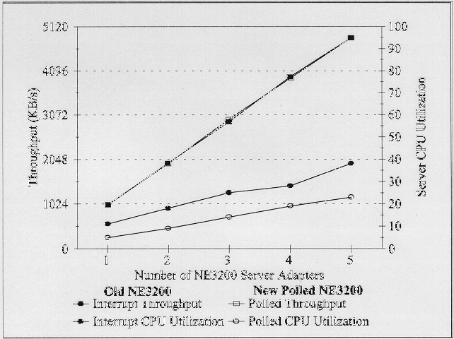
The outcome was a partial success. As shown in Figure 8, the interrupt- and polling-based test results are almost identical. This meant that the software polling model successfully maintained the same high levels of throughput as the interrupt model. At the same time, the CPU utilization for the polling model was half that of the interrupt model. These appeared to be exactly the results we were looking for.
Figure 8: NE3200 performance with interrupt- and polling-based LAN drivers.
However, under very heavy loads the adapter could become saturated - a situation in which it wasn't polled frequently enough. This was a result of two interrelated events: (1) heavy traffic and (2) a large OS run queue of other processes vying for CPU time. When these two events occur simultaneously, the polling frequency declines. Unfortunately, this happens at a time when the polled LAN adapter requires an increase in polling frequency.
In these cases the combined inbound and outbound packet traffic would overrun the adapter buffer, resulting in an eventual loss of packets. Because NetWare's protocols provide for resending dropped packets, no data was lost, but performance suffered. The performance and decreased CPU utilization we derived from the polled driver were good, but we needed a way around the polling frequency problem.
A Hybrid Design: Polling with Interrupt Backup
Eventually, we tried a hybrid design that provided a balance between the benefits of polling under normal conditions and the drawbacks of polling under very heavy loads. This hybrid is called polling with interrupt backup. Polling with interrupt backup allows the adapter to operate in a polled mode until a certain level of utilization is reached, at which time the adapter is allowed to interrupt the server CPU. This combination is the best of both worlds and is implemented in the current NE3200 driver.
|
Custom Statistics in MONITOR.NLM MONITOR displays two statistics that describe the actions taken by an NE3200 when it's operating in polling with interrupt backup mode: Polling Timeout Number of Interrupts Fired Polling timeout. The adapter firmware sets a timer each time it receives a packet. During an on-board pollingprocess the adapter reads this timer and comparesit to a pre-determined time-out value. Ifthe timer is greater than this value, aninterrupt is generated and the Polling timeoutcount is incremented. Number of interrupts fired. This statistic is the total number of interrupts fired by the adapter. Interruptsare generated when the adapter experiences a polling timeout (described above) or when the adapter's receive and transmit buffersare nearly full. To view these statistics, choose the LAN/WAN menu option, select theNE3200 driver, then scroll down to the Custom Statistics section of the screen. |
Benefits of the NE3200 as an I/O Subsystem
With its current architecture, the NE3200 is a true I/O subsystem because it independently handles the complete I/O operation--packet receive/transmit, processing, and data transfer. Acting as an I/O subsystem, the current NE3200 design dramatically lowers server CPU utilization by implementing the following features:
It uses an on-board microprocessor to off-load ECB processing from the server CPU to the LAN adapter
It uses full EISA bus master capabilities, including burst access cycles, to off-load data transfer responsibilities from the server CPU to the LAN adapter
It uses software polling to reduce the number of asynchronous events serviced by the server CPU
The result of this intelligent architecture provides you with the flexibility to broaden the server LAN channel with additive performance.
Additive Performance
Multiple dumb adapters in the server LAN channel provide little additional bandwidth because of their reliance on the host CPU. The phrase "additive performance" refers to the ability of intelligent LAN adapters to add nearly the same bandwidth to the configuration as the first adapter. This capability allows you to design a server LAN channel with multiple LAN adapters and effectively multiply your bandwidth by the number of adapters in the channel.
Our performance measurements in Figure 9 demonstrate the benefit of using intelligent adapters as I/O subsystems in the LAN channel.
Figure 9: Server performance with six intelligent NE3200 adapters (each data point represents a single PERFORM2 test).
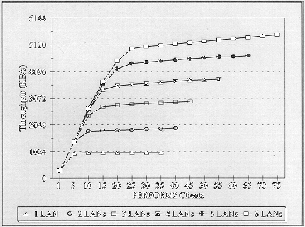
The PERFORM2 tests plotted in Figure 9 used six NE3200s to attach six separate Ethernet LAN segments into one server LAN channel. The y-axis is in 1MB increments so you can see the additive results produced with the addition of each NE3200 (Ethernet's 10Mbps speed translates to a theoretical maximum of approximately 1.1MBps). With three adapters in the server, we reached a maximum throughput of nearly 3MBps. With six adapters, we produced over 5MBps of combined throughput.
These NE3200 results validate the benefits of intelligent LAN adapters specifically designed for NetWare servers. Since the time of these validations in 1989, Compaq, IBM, and Intel have all improved upon the original design.
Performance Gains with Fast Ethernet Server Adapters
Fast Ethernet's 100Mbps transmission rate brings significant benefits to both servers and clients, including:
Increased throughput for server LAN channels
Increased throughput for individual clients
Increased throughput for network segments
Faster response times
At ten times the speed of traditional 10Mbps Ethernet, Fast Ethernet provides the necessary bandwidth you need to expand your network infrastructure, deploy bandwidth-intensive applications, and consider running licensed applications off centralized servers.
As in the 10Mbps Ethernet adapter market, there will be many dumb Fast Ethernet adapters vying for market share. However, dumb Fast Ethernet adapters won't provide the bandwidth capabilities of intelligent server adapters. Not only do the same principles apply to Fast Ethernet, but the need for I/O subsystems in Fast Ethernet server configurations is even greater. This is because Fast Ethernet provides a conduit for ten times the packet volume of traditional Ethernet into the server.
For instance, one server configured with Ethernet may be servicing 3,000 packets per second, while another configured with Fast Ethernet is servicing 30,000 packets per second. This increased load on the server places greater responsibility on the system integrator or manager to off-load as much of the LAN channel processing from the server CPU as possible.
In response, Intel, in partnership with Novell, has designed an intelligent Fast Ethernet adapter that uses the NE3200 as its model. The same principles that applied to the NE3200 design, as well as the resulting benefits, apply to Intel's adapter.
The Intel EtherExpress PRO/100 family of Fast Ethernet adapters include one dumb (non-intelligent) adapter and one intelligent adapter:
Intel EtherExpress PRO/100 Adapter (EISA or PCI)
Intel EtherExpress PRO/100 Smart Adapter (PCI)
Although both will run in NetWare servers, the PRO/100 Smart Adapter is the intelligent adapter designed specifically for server LAN channel configurations.
Using Dumb PRO/100 Adapters in the Server
The dumb PRO/100 adapter has full bus master capabilities and is capable of throughput approaching 10MBps. However, the adapter's reliance on the host CPU to perform packet processing can produce high levels of CPU utilization. Without an on-board microprocessor, the PRO/100 is unable to take full advantage of NetWare's LAN channel capabilities.
To make our point, we configured a server LAN channel with four dumb PRO/100 adapters. Figure 10 shows our PERFORM3 measurements using a y-axis in 10MBps increments (Fast Ethernet's 100Mbps transmission rate translates into a maximum theoretical bandwidth of 10MBps).
Figure 10: Server performance with four dumb PRO/100 adapters.
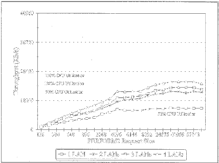
A single PRO/100 adapter in the server-attached to a single LAN-performed very well at more than 7MBps with a modest CPU utilization of 50%. But as additional dumb adapters and LAN segments were added to the configuration, the CPU became a bottleneck, the additive benefits of the additional cards stalled, and throughput suffered. These results demonstrate the general principle that production servers shouldn't be configured with more than a single dumb adapter.
Using Intelligent PRO/100 Smart Adapters in the Server
The PRO/100 Smart Adapter, on the other hand, is designed with the same principles in mind as the NE3200 but with much faster components. For example, the NE3200 used an 80C186Ca 16-bit microprocessor that used an average of eleven CPU clock cycles for each instruction and four CPU clock cycles for every 16-bit memory access. The intelligent adapter, on the other hand, uses an i960Ca 32-bit RISC microprocessor that can execute multiple instructions in a single clock cycle. The i960 can also perform 32-bit memory accesses in bursts of four sequential operations.
The PRO/100 Smart Adapter specifications include:
An i960 microprocessor with an internal 4KB cache
2MB of zero-wait state burst access DRAM for code and packet data
A PLX PCI Bus Master Interface Controller
An Intel 82556 LAN Controller
With this architecture, Intel's server adapter successfully produces an I/O subsystem that off-loads the majority of LAN channel processing from the server CPU onto the adapter.
To test this server adapter's I/O subsystem capability, we used the same four-LAN configuration as in Figure 10, but this time with four PRO/100 Smart Adapters. Figure 11 charts our PERFORM3 measurements using a y-axis in 10MBps increments (Fast Ethernet's 100Mbps transmission rate translates into a maximum theoretical bandwidth of 10MBps).
Figure 11: Server performance with four intelligent PRO/100 Server Adapters.
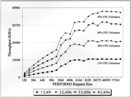
This time we saw dramatic improvements in total server bandwidth. As with the NE3200, these adapters produced additive performance gains- each additional adapter produced nearly 10MBps of additional server LAN channel bandwidth.
With one PRO/100 Smart Adapter attached to a single LAN, the server achieved a maximum throughput of 10.4MBps. The CPU utilization was a paltry 13% compared to the 50% utilization required by a single dumb adapter.
At its peak, with four adapters, the server was responding to its clients with 38MB of data per second. The server was handling over 27,000 packets every second, with a CPU utilization of only 59% compared to half the throughput and double the CPU utilization of dumb adapters as in Figure 10. Using the intelligent adapters, the majority of LAN channel processing is distributed to the adapter microprocessors.
Interrupts vs. Polling
Part of the performance gains produced by the server adapter are due to the use of software polling. As with the NE3200, the PRO/100 Smart Adapter's design goal was to off-load as much processing from the host CPU as possible. Removal of interrupt overhead was an important milestone in reaching that goal.
Figure 12 charts the results of our PRO/100 Smart Adapter driver benchmarking with both interrupt- and polling-based drivers. The results show that, in this test configuration, the polled driver improved performance over the interrupt-based driver by 50%.
Figure 12: PRO/100 Server Adapter performance using interrupt- and polling-based LAN drivers.

These results are a clear indication that the PRO/100 Smart Adapter performs most efficiently in a polled mode.
Measuring Polling Process Frequency with STAT.NLM
NetWare's Polling Process can execute thousands of times each second whenthe server is idle. However, a more interesting statistic is thenumber of times the Polling Process executes while your serveris servicing a production workload.
Using STAT.NLM you can record the minimum and maximum number of times the polling process has executed per second. Summary A is a STAT summary file (.SUM) from a Compaq SystemPro 386/33 with 250 benchmark clients. Before the benchmarkstarted (while the server was idle) STAT recorded 122,450 PollingProcess loops. During the benchmark's peak load, STAT recorded a minimum of 9,753 Polling Process loops. So even under a strenuous load, NetWare was executing the Polling Process nearly 10,000 times per second.
----------Summary A (using DUMPSTAT v1.0) ---------
Start Time:   Fri Jul 22 09:32:24 1994
End Time:   Fri Jul 22 22:42:19 1994
Elapsed Time:  13:09:55
Records Read:  47,393
Records Written:  789
Minimum Polling Loops: 9,753
Maximum Polling Loops: 122,450
Summary B is a STAT summary taken from the server used for the Fast Ethernet testing in this AppNote (see Figure 13) while the server was idle. The Polling Processreached a maximum of over 313,000 times every second.
---------Summary B (using DUMPSTAT v1.0) ---------
Start Time:   Wed Mar 15 20:31:38 1995
End Time:   Wed Mar 15 20:31:49 1995
Elapsed Time:  00:00:11
Records Read:  11
Records Written:  11
Minimum Polling Loops: 127,207
Maximum Polling Loops: 313,729
Summary C is from the same server while it serviced 64 full-motion video clients. During the test, at the same time the LAN channel was transmitting 30.6MB of data, the Polling Process hit a minimum of 25,244 loops per second.
---------Summary C (using DUMPSTAT v1.3) ---------
Start Time:   Wed Mar 15 20:35:52 1995
End Time:   Wed Mar 15 20:36:20 1995
Elapsed Time:  00:00:28
Records Read:  28
Records Written:  28


Statistic Ranges     Minimum/sec.   Maximum/sec.
Polling Loops:       25,244         90,767
Bytes Received:      129,131        449,260
Bytes Transmitted:   9,199,592      32,125,188
Disk Bytes Read:     262,144        2,744,320
Disk Bytes Written:  0              6,144
Packets Routed:      0              0
Stations In Use:     67             67
This points out two important characteristics of NetWare'sPolling Process. First, the frequency of the Polling Process decreasesas the server's workload increases. Second, under very high throughput conditions, the decreased polling frequency is more than sufficient to handleLAN channel event scheduling.
STAT.NLM and DUMPSTAT.EXE can be downloaded from NetWire. Look for STAT.ZIP in NovLib 11.
Conclusion
As demonstrated in this AppNote, intelligent LAN adapters provide significant benefits over dumb adapters in terms of LAN channel bandwidth and server growth capability. By using intelligent LAN adapters as I/O subsystems, you can offload LAN channel processing from the server's CPU, leaving it free for core processing tasks and key server applications.
We recommend that network designers, implementers, and managers use intelligent LAN adapters with this kind of architecture in both single- and multiple-adapter server LAN channel configurations.
How We Tested the Server LAN Channel
Four different test configurations were used to produce the performance charts in Figures 8, 9, 10, 11, and 12. This section describes relevant configuration details and the test workloads used to measure performance.
The PCI Server Platform
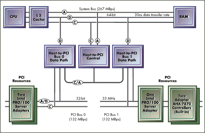
The Fast Ethernet results in this AppNote were produced on an AT&T GIS with a 100MHz Pentium and two peer PCI busses. The server uses a three-component bridge that allows the PCI busses to operate concurrently with one another and the processor- each with a peak throughput of 133MBps. This bus configuration is an improvement over a cascaded arrangement in which the second bus shares the bandwidth of the first (see Figure 13).
Figure 13: Server architecture with two peer PCI busses.
Test Workloads
PERFORM2. PERFORM2 is a Novell benchmark written in 1986 to measure LAN channel performance. Now out-dated, PERFORM2 isolates the LAN channel from the disk channel by measuring the performance of multiple clients reading from a shared block of data in server cache. Results from this test workload represent the maximum achievable throughput using 4KB read requests. Production workloads with a smaller packet size distribution than the test workload will see diminished results.
PERFORM3. PERFORM3 is the Novell benchmark that replaced PERFORM2 in 1989. In addition to isolating the LAN channel, PERFORM3 allows read requests up to 64KB in size. PERFORM3 results are the maximum achievable throughput using 64KB read requests. Production workloads with a smaller packet size distribution than the test workload will see diminished results.
Test Configurations
NE3200 Polling Trials (Figure 8). The polling trials displayed in Figure 8 were run in 1994 during the development of the polling NE3200 LAN driver. These tests used PERFORM3. The server was a Compaq SystemPro XL with a 486/50 CPU and EISA expansion bus.
NE3200 Benchmarks (Figure 9). The polling trials displayed in Figure 9 were run in 1989 during the development of the NE3200 LAN adapter. These tests used PERFORM2. The server was a Compaq SystemPro with a 383/33 CPU and EISA expansion bus.
Intel EtherExpress PRO/100 Adapter Benchmarks (Figure 10). The Fast Ethernet benchmarks displayed in Figure 10 were run in 1995.
The server was an AT&T GIS with a 100MHz Pentium and dual PCI busses described above. The LAN channel included four Intel EtherExpress PRO/100 Adapters (PCI). The disk channel included two built-in Adaptec 7870 PCI Fast and Wide SCSI controllers with three Quantum Atlas drives attached to each.
The test clients included twelve AT&;T Globalyst 66Mhz Pentium PCI Desktops, three on each LAN segment. Each client used an Intel EtherExpress PRO/100 Adapter (PCI)
Intel EtherExpress PRO/100 Smart Adapter Benchmarks (Figure 11). The server adapter benchmarks in Figure 11 used the same configuration as the dumb adapter benchmarks in Figure 10 with the exception of the server adapters.
The server was an AT&;T GIS with a 100MHz Pentium and dual PCI busses described above. The LAN channel included four Intel EtherExpress PRO/100 Adapters (PCI). The disk channel included two built-in Adaptec 7870 PCI Fast and Wide SCSI controllers with three Quantum Atlas drives attached to each.
The test clients included twelve AT&;T Globalyst 66Mhz Pentium PCI Desktops, three on each LAN segment. Each client used an Intel EtherExpress PRO/100 Adapter (PCI).
PRO/100 Smart Adapter Polling Trials (Figure 12). In the polling trials, we used PERFORM3 to test two different LAN drivers- one designed to use interrupts and the other designed for software polling.
The server was an AT&;T GIS with a 100MHz Pentium and dual PCI busses described above. The LAN channel included four Intel EtherExpress PRO/100 Adapters (PCI). The disk channel included two built-in Adaptec 7870 PCI Fast and Wide SCSI controllers with three Quantum Atlas drives attached to each.
The test clients included twelve AT&;T Globalyst 66Mhz Pentium PCI Desktops, three on each LAN segment. Each client used an Intel EtherExpress PRO/100 Adapter (PCI).
* Originally published in Novell AppNotes
Disclaimer
The origin of this information may be internal or external to Novell. While Novell makes all reasonable efforts to verify this information, Novell does not make explicit or implied claims to its validity.