Effectively Managing RIP and SAP Traffic with Filtering
Articles and Tips: article
Senior Technical Marketing Manager
Corporate Marketing
JOE GERVAIS
Product Marketing Engineer
NetWare Enterprise Products
01 Sep 1994
This Application Note is the first in a three-part series on managing Routing Information Protocol (RIP) and Service Advertising Protocol (SAP) traffic. It provides an overview of the operation of RIP and SAP, and describes how to use RIP and SAP filtering to reduce bandwidth requirements on a wide area network (WAN). Subsequent Application Notes will examine how to manage RIP and SAP traffic with NetWare/IP software on a WAN and also how to migrate from RIP and SAP to the NetWare Link Services Protocol (NLSP).
This AppNote supersedes "Managing SAP Information with the NetWare Service Advertising Filter (SAFILTER) v1.00" in the July 1992 issue. Some portions of this AppNote were derived from "NetWare Communications Processes" in the September 1990 NetWare Application Notes. Readers should refer to that AppNote for background information about Internet Packet ExchangeTM(IPXTM) and NetWare Core ProtocolTM (NCPTM), as well as client RIP/SAP operation.
- Introduction
- Routing Information Protocol (RIP)
- Service Advertising Protocol (SAP)
- Routing Information Broadcasts
- Service Advertising Broadcasts
- RIP and SAP Bandwidth Requirements
- Controlling Traffic with RIP/SAP Filtering
- RIP/SAP Filtering with MultiProtocol Router
- Summary
Introduction
Novell's Routing Information Protocol (RIP) and Service Advertising Protocol (SAP) are integral to the operation of the NetWare operating system. This AppNote provides an overview of RIP and SAP, and describes how to use RIP and SAP filtering to reduce bandwidth requirements on a wide area network (WAN). It also describes how to use RIP/SAP filtering with the NetWare MultiProtocol RouterTM.
Note: Throughout this AppNote, references are made to the TRACK ON screen. With a standard NetWare server, issuing the TRACK ON command creates a console screen that logs all RIP and SAP traffic on the server. When the IPXRTR NetWare Loadable ModuleTM(NLMTM) is installed on a server, issuing the TRACK ON command creates a console screen that logs all RIP traffic on a server and a second console screen that logs all SAP traffic on a server. TRACK OFF turns off the tracking of RIP and SAP traffic in both cases.
(IPXRTR.NLM is Novell's implementation of NLSP; it also includes several other major enhancements to IPX routing. Information will be available later this year on the NetWire electronic bulletin board and by anonymous FTP on how to obtain IPXRTR.NLM for NetWare 3 and NetWare 4 servers.)
Routing Information Protocol (RIP)
Routers use the RIP to inform one another about which networks can be reached. Each router creates and maintains a dynamic database of internetwork routing information. This database is the router's view of the network topology. Only networks included in the router's database can be reached through the router.
Like IPX, RIP was derived from the Xerox Network System (XNS) protocols. However, Novell added an extra field to the packet structure to improve the decision criteria for selecting the fastest route to a destination. This change prohibits the straight integration of NetWare RIP with other undeviating XNS implementations.
RIP Packet Structure
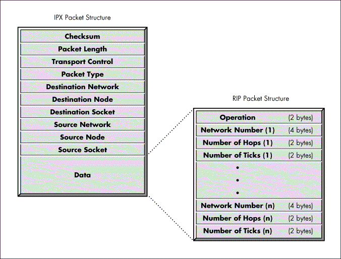
The structure of a RIP packet is shown in Figure 1. This structure is enveloped within the data area of IPX.
The Operation field indicates whether the packet is a request or a response. A 1 in this field indicates a request and a 2 indicates a response. The Operation field can be followed by one or more (n) sets of information, each consisting of a network number and the number of hops and ticks to that network number. By default, a RIP packet can contain a maximum of 50 sets of network number information.
Figure 1: The RIP packet contains information about available networks.
With NetWare 4, the number of network entries in a packet can be adjusted. In addition, NetWare 4 allows the periodic broadcast interval to be adjusted from the default of every 60 seconds. These periodic broadcasts keep all routers on the internetwork synchronized, and provide a means of "aging" (removing after a certain timeout) those networks that might become inaccessible because of a router failure. Networks are typically aged from the routing database in three minutes following the last receipt of an advertisement for that network.
Hops. The term "hops" refers to the number of routers that must be passed through to reach a network number. This value is placed in the Number of Hops field.
Ticks A "tick" is roughly 1/18 of a second (there are 18.21 ticks in a second). The number of ticks measures how much time the packet takes to reach a network number. The value in the Number of Ticks field is always at least one.
The original XNS definition of RIP did not include the Number of Ticks field. The developers of NetWare added the Number of Ticks field so that the NetWare shell could estimate how long it should wait for a response from a file server. Also, if multiple routes exist to a network number, a router uses the route with the shortest number of ticks when forwarding packets to that network number.
Note: In the past, many third-party routers did not do tick-based routing. Routers that have passed the Novell Labs IPX Router Certification do routing based on tick count. For a detailed list of these routers, contact Novell Labs.
If a RIP packet is a request for information, only the Network Number field applies; the Number of Hops and Number of Ticks fields are essentially nulled out. A response packet can either be a reply to a request from a router or workstation, or a periodic broadcast by a router.
The single packet structure defined by RIP allows the following exchanges of information:
Workstations locate the fastest route to a network number by broadcasting a route request (represented by a Route Request entry on the TRACK ON screen).
Routers request routing information from other routers to update their own internal tables by broadcasting a route request (represented by a Route Request entry on the TRACK ON screen).
Routers respond to route requests from workstations and other routers.
Routers perform periodic broadcasts every 60 seconds to make sure that all other routers are aware of the internetwork configuration.
Routers perform broadcasts whenever they detect a change in the internetwork configuration.
Service Advertising Protocol (SAP)
SAP allows service-providing nodes such as file servers, print servers, and gateway servers-to advertise their services and addresses. SAP makes the process of adding and removing services on an internetwork dynamic. As servers are booted up, they advertise their services using SAP; when they are brought down, they use SAP to indicate that their services are no longer available.
The primary users of all this information are servers, which store the data in the bindery for easy access. The server creates a bindery object using the advertised name and type for each advertising entity not residing on the server. The object created is dynamic, and is deleted when the file server is brought down. Every dynamic object created by SAP has a single property, NET_ADDRESS, which contains the full IPX internet address (net, node, and socket) of the advertising server.
With NetWare 4, this information is stored in the dynamic bindery partition. These are the bindery objects seen when a user runs a utility such as SYSCON, SLIST, or PCONSOLE to look at the list of known services.
Through SAP, clients on the network can determine what services are available on the network and obtain the internetwork address of the nodes (servers) where they can access those services. This is an important function, because a workstation cannot initiate a session with a file server without first having that server's address.
By default, all servers advertising with SAP (file servers, print servers, and SAA gateway servers, for example) broadcast a SAP packet every 60 seconds onto the network segment it is connected to. The SAP agent in each router on that segment copies the information contained in the SAP packet into an internal table called the Server Information table.
Because the SAP agent in each router keeps up-to-date information about available servers, a client wanting to locate an SAA gateway server can access a nearby router for the correct internetwork address of the gateway server.
SAP Packet Structure
Like RIP, SAP uses IPX and the medium access protocol for its transport. Figure 2 illustrates the structure of a SAP packet.
Figure 2: The SAP packet contains information about advertising servers.
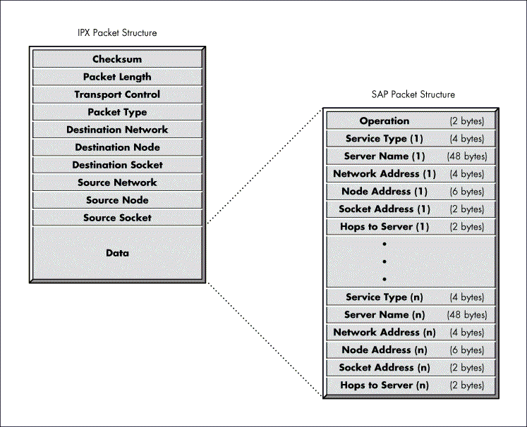
The Operation field defines the operation that the packet is performing. The packet can perform five different operations:
A workstation request for the name and address of the nearest server of a certain type (this is represented by a Get Nearest Server entry on a TRACK ON screen).
A general request, by a router, for the names and addresses of either all the servers or all the servers of a certain type on the internetwork (represented by a Send All Server Info entry on the TRACK ON screen).
A response to either a Get Nearest Server request (represented by a Give Nearest Server entry on TRACK ON screen) or a general request.
Periodic broadcasts by servers and routers.
Changed service information broadcasts.
Following the Operation field are one or more sets of fields. Each set includes Service Type, Server Name, Network Address, Node Address, Socket Address, and Hops to Server fields. If the packet contains information about more than one service, it contains more than one set of fields (n sets of fields). Each SAP packet can contain information about up to seven services.
With NetWare 4, the number of SAP entries per packet can be adjusted. In addition, NetWare 4 allows the periodic broadcast interval to be adjusted from the default of every 60 seconds. These periodic broadcasts keep all routers on the internetwork synchronized and provide a means of "aging" (removing after a certain timeout) those services that might become inaccessible because of a router or server failure. Service names are typically aged from the routing database in three minutes following the last receipt of an advertisement for that service name.
Routing Information Broadcasts
On an internetwork, routers are constantly exchanging information with each other to make sure that their Routing Information tables reflect up-to-the-minute changes in the layout of the internetwork. To accomplish this, routers transmit a series of broadcasts from the time they come up until they are brought down.
These broadcasts can be separated by the time at which they occur:
Initial broadcast of directly connected network segments
Initial request to receive routing information from other routers
Periodic broadcasts (every 60 seconds) of the current list of active network numbers
Broadcast of change in internetwork configuration
Final broadcast when brought down
Although the broadcasts occur at different times and, for the most part, contain different information, they must follow two important rules. First, each broadcast must be a local broadcast, addressed so that it is not immediately passed on, intact, by the routers that receive it. This reduces the network traffic created by these information exchanges. Second, routers must follow a "split horizon" algorithm when providing information to other routers through a broadcast (because the second broadcast listed above is a request for information, this rule does not apply to it).
Split Horizon Algorithm
The purpose of routing information broadcasts is two-fold: to allow a router to share its current impression of the layout of the internetwork with other routers, and to inform the routers of an internetwork change so the routers can update their tables.
A router sends routing information broadcasts to every network segment that it is directly connected to. The first rule of the split horizon algorithm dictates that a router about to broadcast to a particular network segment should not include any information about other segments that it has received from the segment to which the information is being sent.
|
In previous Novellpublications, the split horizon algorithmwas referred to as the "best information algorithm." |
For example, suppose the router within server FS2 in Figure 3 is going to broadcast a routing information broadcast to network segment BB. In this example, FS2's router would not include information that it received from FS1 about network segment AA. If it did, someone on segment BB might erroneously conclude that there are two paths to segment AACone through FS1 and another through FS2.
Figure 3: When broadcasting routing information, routers follow the rules specified in the split horizon algorithm.
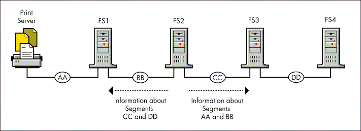
The split horizon algorithm also states that routers should not include information about the network segment that they are sending routing information broadcasts to. For example, FS2 would not include information about BB in its broadcast onto BB.
Taking these rules into account, the information that FS2 would broadcast onto segment BB would be information about segments CC and DD.
Initial and Periodic Broadcasts
When a router is first brought up, it places the network numbers of its directly connected segments into its Routing Information table. Then, following the split horizon algorithm, the router sends a routing information broadcast to inform the routers on its directly connected segments of the segments that the router is making available (see "a" in Figure 4).
Figure 4: The initial sequence of routing information broadcasts.
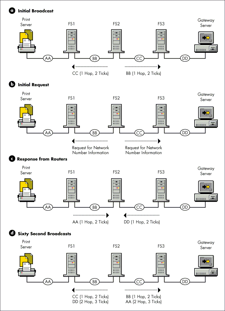
The router next broadcasts a request to each of its directly connected segments for information about all other network segments that exist on the internetwork (see "b" in Figure 4). This request is responded to by all the routers (each using the split horizon algorithm) on these directly connected segments (see "c" in Figure 4). The router places the information gleaned from these responses in its Routing Information table.
Once the router performs these initial broadcasts and updates its Routing Information table, it is ready to accept routing requests and route packets. In addition to routing packets, the routers broadcast all the information in their Routing Information table (except that excluded by the split horizon algorithm) to each of their connected network segments every 60 seconds.
Routers perform these periodic broadcasts to make sure that all routers on the internetwork remain synchronized (see "d" in Figure 4). Routers retain this information for three update intervals before marking the information invalid. This ensures that routes are not deleted due to a dropped packet or other errors.
Changed Information Broadcasts
When a router receives information that causes it to change its Routing Information table, the router immediately passes that information to its other directly connected network segments, except for the segment that the router received the information from. If a new network segment comes up or an existing segment goes down, all the routers on the internetwork learn about the change in a short amount of time.
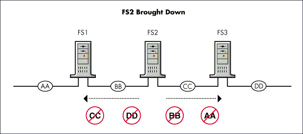
The primary cause of a change in the internetwork's configuration are file servers and external routers coming up or going down. If a router needs to be brought down (using the DOWN command at the NetWare system console), the router informs its directly-connected segments of the fact before discontinuing service. The router issues broadcasts (using the split horizon algorithm) that indicate that the network segments that the router had made available are no longer accessible through this router (see Figure 5).
Figure 5: When a router is brought down, it tells other routers which segments are no longer accessible through its router.
The Aging Process
If a router goes down due to a hardware failure, power glitch, or power outage, other routers are not notified that a change has occurred. To safeguard against this eventuality, an "aging" mechanism has been built in to NetWare routers.
Routers maintain a timer for each entry in their Routing Information table. By default, the timer expires after three minutes. However, with NetWare 4 and many third-party routers, this time is adjustable, usually on a per-interface basis. Every time that information is received concerning the entry, the timer is reset to zero.
If the timer reaches three minutes, the router assumes that the route to the network number is down and broadcasts that fact to its other segments. Because this information about the expired route is new or changed, the routers that receive the information pass it on immediately and the change quickly permeates the internetwork.
Service Advertising Broadcasts
Using SAP, servers on a NetWare network can advertise their services and addresses. The information that these servers broadcast is not used directly by clients, but is instead collected by a SAP agent within each NetWare router on the server's segment. The SAP agents store this information in a Server Information table and, if they reside within a server, in their server's bindery. The clients can then contact the nearest SAP agent or file server for server information.
The SAP broadcasts that servers perform are local broadcasts and, therefore, are only received by SAP agents on their connected segments. Consequently, SAP agents periodically broadcast their server information so that all SAP agents on the internetwork have information about all servers that are active on the internetwork. This is the same broadcast method used by routers to distribute and exchange network number (RIP) information.
Server Information Table
The table that SAP agents use to store information received in SAP broadcasts is called the Server Information table. If all SAP agents on the internetwork are exchanging SAP information properly, each agent's Server Information table should have information about all the servers on the internetwork thus providing clients with nearby access to the addresses of all the servers on the internetwork.
Figure 6 illustrates some of the more pertinent fields of the Server Information table.
Figure 6: SAP agents store information about available services in their Server Information Tables.
|
Server Name
|
Server Address
|
ServerType
|
Hops toServer
|
Time SinceChanged
|
NICNumber
|
|
FS1 |
000000AA:000000000001 |
107 |
1 |
:29 |
1 |
|
FS2 |
000000AA:000000000001 |
4 |
1 |
:29 |
1 |
|
FS3 |
000000DD:000000000001 |
4 |
1 |
:45 |
2 |
|
0001B1E2D9D000000BB |
000000BB:00001B1E2D9D |
026A |
1 |
:36 |
1 |
The Server Address field contains the service's full address, including network, node, and socket addresses.
The Server Type field holds a number designating what type of service the server provides. For example, one server might provide printing services as opposed to file services.
The server type designation used to assign numbers to the different services that servers provide is part of a more generic scheme used in the bindery to classify objects. Some of the more common object types are listed in Figure 7.
The Time Since Changed field is used for aging servers that have gone down unexpectedly.
The NIC Number field specifies the NIC that the information about the server was received on.
Figure 7: Common object types found in the Server Type field of the Server Information Table.
|
Description
|
Type
|
Socket
|
|
File Server |
4 |
451 |
|
Advertising Print Server |
47 |
8060 |
|
Btrieve |
4B |
8059 |
|
NetWare SQL |
4C |
805B |
|
Named Pipes |
9A |
9100 |
|
Remote Console |
107 |
8104 |
|
NetWare ManagementAgentTM 1. 5 |
233 |
2F90 |
|
NetExplorer™ |
237 |
401F |
|
Hub ManagementInterface™ Hubs |
239 |
5204 |
|
NetWare LANalyzerAgent™ |
23A |
0 |
|
NetWare Connect™ |
24E |
1B90 |
|
NMS Console |
26A |
0 |
|
Time Synchronization |
26B |
4005 |
|
NDS™ Replica |
278 |
4006 |
|
Remote NLM Spawn (RSPAWN) |
9000 |
9085 |
The way that information is stored within the Server Information table makes sequential access (for instance, "send me information about all servers with server type 4") possible. However, it makes database access ("send me information about server NCS") very difficult.
Therefore, the Server Name, Server Address, Server Type and Hops to Server fields of the Server Information table are periodically copied to file server binderies by internal SAP agents that reside within file servers. With this information stored in file server binderies, any client that has a connection with a NetWare file server can query the bindery for the address of a specific server.
Server Information Administration
Figure 8 illustrates the initial and periodic broadcasts performed by SAP agents. When a file server is first brought up, its internal SAP agent places the name of the server in the agent's Server Information table. The SAP agent then sends SAP broadcasts onto each of its directly connected segments to inform the SAP agents on those segments that a new server has become available (see "a" in Figure 8.)
Figure 8: The SAP agent sends SAP broadcasts to connected segments.
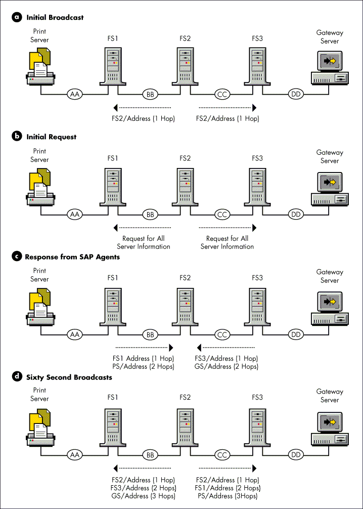
After performing its initial broadcasts, the SAP agent broadcasts a request onto each of its directly connected segments for information about other servers that exist on the internetwork (see "b" in Figure 8). These requests are responded to by all the SAP agents on these directly connected segments (see "c" in Figure 8). The SAP agent places the information received in these responses in its Server Information table.
Thereafter, the SAP agent performs broadcasts about the servers that it is aware of every 60 seconds (see "d" in Figure 8). Routers retain this information for three update intervals before marking the information invalid. This ensures that services are not deleted due to a dropped packet or other errors.
As with routing information broadcasts, all server information broadcasts are local broadcasts and are subject to the split horizon algorithm. Any changes in server information are passed on immediately to ensure current information across the internetwork.
The router applies the aging process to its Server Information table entries in case any servers become unavailable.
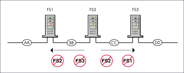
Finally, if the router is brought down gracefully by issuing the DOWN command at the NetWare system console, it indicates to its directly connected segments that the servers the router has been advertising are no longer available (see Figure 9).
Figure 9: When a router is brought down, it informs other routers of servers that are no longer available.
RIP and SAP Bandwidth Requirements
On LAN segments, the traffic caused by RIP and SAP broadcasts does not cause a significant load. On large internetworks with several hundred servers, however, administrators become concerned with the load that RIP and SAP broadcasts place on their WAN segments. The requirements and some examples are shown in Figure 10.
Figure 10: Bandwidth requirements for default 60-second periodic broadcasts.
RIP updates over 802.2 Ethernet/Token Ring/FDDI
|
3 networks |
73 bytes/minute |
10 bps |
|
53 networks |
520 bytes/minute |
69 bps |
|
1000 networks |
8940 bytes/minute |
1132 bps |
SAP updates over 802.2 Ethernet/Token Ring/FDDI
|
3 services |
239 bytes/minute |
32 bps |
|
53 services |
4768 bytes/minute |
636 bps |
|
1000 services |
70,721 bytes/minute |
9430 bps |
As you can see, the SAP broadcasts for an internetwork containing 1000 servers account for less than one percent of the total bandwidth (10 megabits per second) of an Ethernet segment. The RIP traffic is even less significant. It may seem that the SAP bandwidth requirements don't become substantial until the network is quite large, with 1000 or more services.
However, it is quite easy in a moderately sized network to construct a wide area network that experiences significant SAP traffic problems. For example, take a network with 200 services, and build a frame relay network interconnecting 10 branches to a headquarters location. In this example, the headquarters router would be responsible for broadcasting 2000 services a minute, which would consume about 40 percent of a 56 kbps circuit.
Another point to make here is that SAP traffic is significantly more expensive than RIP traffic. Furthermore, many networks have significantly more services than network segments, usually on the order of twice as many services as segments. In light of this, SAP filtering should be the main focus in reducing bandwidth requirements.
Total traffic load of routing and server information broadcasts on any given segment is equal to the traffic generated from broadcasting information about all the network segments and servers that exist on the internetwork.
For example, let's look at a star topology network. When examining the traffic on a point-to-point link between two IPX routers, one router broadcasts information about all the network segments and servers that it is making available to the other router (using the split horizon algorithm). The other router broadcasts information about all the segments and servers that it is making available to the first router. The total of the two equals the total number of servers and segments that reside on the internetwork.
The point to consider with star networks is that between any two routers, the total traffic load for all advertised services and networks will be transmitted between the two nodes. However, with multiaccess media (such as frame relay and X.25), there may be many point-to-point conversations.
Controlling Traffic with RIP/SAP Filtering
As networks increase in size and complexity, the quest for improved performance and better management intensifies. On large networks (100 or more servers), a logical place to begin this search is in network packet traffic. One area of network traffic that can be controlled is SAP traffic.
In NetWare networks, SAP is used by servers, print servers, gateways, and so forth to advertise their services. Routers use SAP to exchange necessary routing information. Workstations also use SAP in their initial network attachment to find the "nearest" server. Thus SAP filtering may be 20 times more effective than RIP filtering.
When to Restrict SAP Traffic on the Network
Bridged Networks. Most networks, especially "flat" networks in which each server advertises only itself, experience few problems with SAP traffic.
A bridged network, such as in a source-route-bridged token ring network, appears flat to IPX, but might have issues due to too many servers on a single bridged segment. In this case, filtering is not effective because each server needs to be filtered, which effectively blocks access to the filtered services (see Figure 11).
Figure 11: RIP/SAP filtering is ineffective in this type of network because each server advertises only itself.
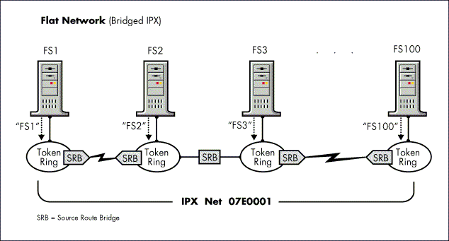
The solution in this case is to migrate to a routed IPX environment. The NetWare MultiProtocol Router software can replace source route bridges with a product that routes IP, IPX, and Appletalk, while also doing the source route bridging.
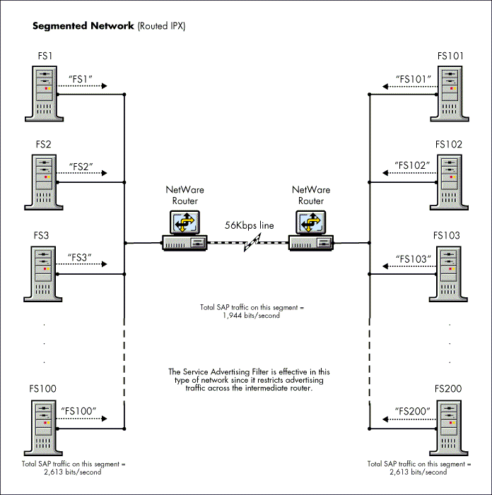
Point-to-Point WAN Links in Large Networks. On large networks, excessive SAP traffic can have a slowing effect on the throughput of network traffic when there is a heavy workload. The larger the network, the greater the potential amount of SAP traffic. It is for these large networks that RIP/SAP filtering provides the greatest benefit (see Figure 12).
Frame Relay and X.25 Links in Moderate Networks. In moderate sized networks, SAP can become a bottleneck, since rather than sending a SAP advertisement for 100 or more services once across the link, it is sent once per remote site across the link from the central site. With a few sites on a 9.6 bps X.25 access circuit or 56 kbps frame relay access circuit, this can easily consume all the bandwidth of the central site access circuit.
Figure 12: RIP/SAP filtering is effective in large internetworks because it can restrict advertising traffic across the routers.
Reducing SAP Traffic from Remote Servers
One of the primary uses of RIP/SAP filtering is to reduce the overall amount of SAP traffic being broadcast across the internetwork. RIP/SAP filtering helps reduce unnecessary network traffic by restricting advertisements for servers that are located at remote offices. By restricting SAP traffic to the servers that are needed by the users, network traffic is reduced on limited bandwidth WAN circuits.
If you have five different branch locations connecting to a corporate location, you can use RIP/SAP filtering to restrict unnecessary SAP traffic. Of course, some locations need access to servers in other locations, but in many cases, only the central resources need to be accessed. Furthermore, certain resources (such as print, backup, and fax servers) might only be useful to the workgroup they serve. These are other advertising devices that can be filtered.
An office in Dallas, for example, might not need access to all the Seattle or New York servers, and neither does the Portland office. The San Jose office might need access to the Portland and Seattle offices, but not necessarily to Miami. After deciding who needs access to which servers, you can use RIP/SAP filtering to regulate the SAP traffic.
The network administrator can use RIP/SAP filtering on the Accounting, Administration, and Engineering servers to restrict which of the Accounting and Administration servers the Engineering network can "see." If each department (Accounting and Administration) has 20 servers but the Engineering network needs access to only two servers in each of those departments, the number of SAP packets can be cut from six to one.
This also prevents users on the Engineering network from seeing servers you want to restrict; however, it does not necessarily restrict their access to these hidden servers.
Using Gatekeepers When SAP Filtering
One problem that occurs when using filtering is user dissatisfaction, because the network is no longer open, and also is more difficult to use. A common method of leaving the network usable while drastically reducing SAP traffic is to employ gatekeepers.
Gatekeepers are servers that have full visibility to the network that the user can use to leapfrog to hidden servers. If we go back to the previous example, where only limited services were required on each remote network, we would set up the following gatekeepers: GK-Dallas, GK-Seattle, GK-New-York, GK-Portland, GK-Miami, and GK-San-Jose. With the GK prefix to the servers, users can do a wildcard SLIST or NLIST to find all the gatekeepers (for example, SLIST GK*).
Attaching to a Remote Server Through a Gatekeeper
When using gatekeepers, workstations on the local LAN cannot attach to services on the remote LAN unless they connect through the gatekeeper using the following method. A prerequisite for using the following method is that at least one gatekeeper is advertised across both of the routers on the WAN link. Furthermore, the gatekeeper should have full visibility to either all servers on the site or all servers on the entire internetwork.
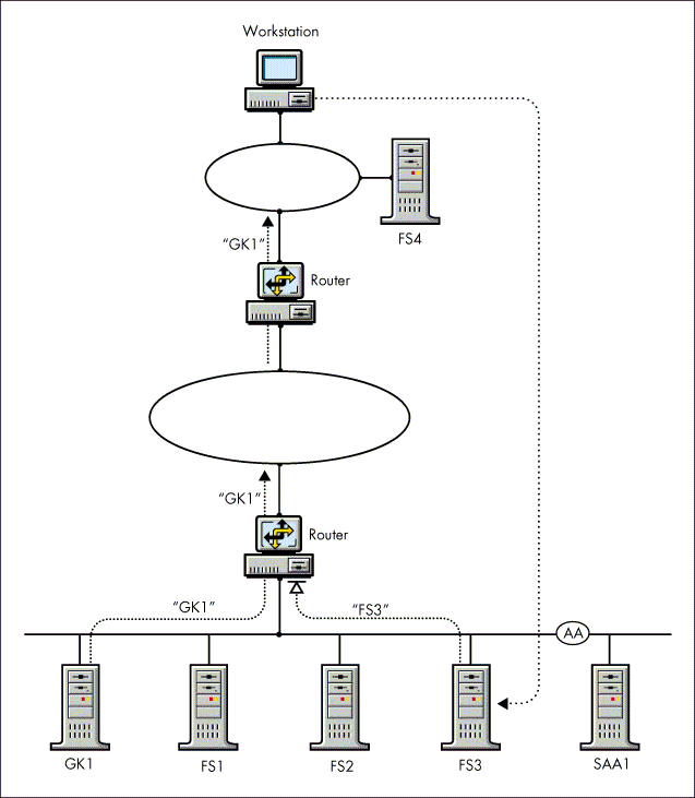
Use the following procedure to attach to a remote server, as illustrated in Figure 13:
Log in from your workstation to the file server on your local LAN (FS4 in this example).
Attach to the file server on the remote LAN (GK1, which is allowed to pass SAP information).
Map a drive to the remote server (GK1).
Change to that drive, and use the SLIST command to see the other file servers (FS1, FS2, and FS3) on the remote LAN. You can now also attach or map drives to them.
Figure 13: In a SAP filtered network, users can attach to a remote servers through a gatekeeper.
Network Security and SAP Filtering
SAP filtering is advantageous to use on large networks that experience a lot of SAP traffic. In the past, SAP filtering has been promoted as a method of solving other types of problems as well. In particular, by controlling the amount of SAP traffic that passes through any server, it was believed that you can also increase your network security.
In many networks, there are usually servers that most users do not need to see or even know about. For instance, people in the Engineering department probably do not need to see or access servers in Accounting, Sales, or most other departments. By using RIP/SAP filtering, you can control what servers are visible to which users.
It was believed that because users cannot log in to servers they can't "see," SAP filtering allowed you to control user access to these servers. The flaw in this logic is that a user does not need an account on a system that has visibility to the hidden servers to gain access to a hidden server.
A user can leapfrog to a hidden server by attempting to attach to any NetWare system (gatekeeper) that has visibility to the hidden system. This method does not work if the gatekeeper does not have a bindery, such as is the case with a third-party IPX router.
A router using inbound RIP and SAP filters restricts users from accessing some or all network services that would be advertised to that router. It is usually desirable to prevent routers that are restricted (by IPX RIP/SAP filters) from responding to the "Get Nearest Server" request, so that clients that require access to many servers do not attach to them.
Clients that require unrestricted access should also be configured with a "Preferred Server" command in their NET.CFG file (before the driver commands). This is particularly true for LAN segments that have a single point of entry that is restricted by filters.
The following is an example of the "preferred server" command:
PREFERRED SERVER=servername
Filtering RIP
The view of the network created from RIP broadcast packets can be configured by removing network address entries from RIP packets. This aids in controlling network access by limiting services that are reachable from different sections of the internetwork.
Remember, it is generally undesirable to filter RIP to save bandwidth. SAP typically requires 20 times the bandwidth of RIP, and filtering only SAP doesn't prevent network access whereas RIP filtering does. RIP filtering should only be used for security purposes.
Caution: With SAP filtering, even though you can't see services, by knowing a gatekeeper to the services you can still reach the service. With RIP filtering, if there is no route in a router along the path to the destination, the packets cannot be forwarded to the destination and are discarded. Furthermore, if no route exists for a service, the service is not added into the bindery of NetWare servers. Extreme caution should be used any time RIP filtering is considered.
When attempting to use RIP filtering for security, filtering should be done inbound rather than outbound when possible. Outbound filtering can potentially be bypassed by placing a static route that points to the router doing outbound filtering in a router that is not receiving the filtered route. This allows the router doing outbound filtering to still receive packets to destinations the router is filtering route advertisements.
With inbound filtering, the router doing the filtering must be compromised to breech security.
Filtering NetBIOS Packets
For certain protocol implementations (such as NetBIOS) to function in the NetWare environment, routers must allow a broadcast packet to be propagated throughout an internetwork. The IPX Packet Type 20 is used specifically for this purpose.
NetBIOS filtering provides the capability of stopping the propagation of these internetwork broadcasts, which is particularly useful for preventing NetBIOS broadcast storms over WANs.
Use of the IPX Packet Type 20 filter only applies to NetBIOS packets sent using the IPX protocol. It does not affect NetBIOS packets that are bridged or routed using other protocols.
RIP/SAP Filtering with MultiProtocol Router
The IPX RIP/SAP filter was provided as an enhancement to NetWare MultiProtocol Router 2.1 or NetWare MultiProtocol Router Plus 2.1 software through NetWire and NSE Pro in the RIPSAP.EXE and FRELAY.EXE patches. It is also included in NetWare MultiProtocol Router 2.11 and NetWare MultiProtocol Router Plus 2.11.
Prior releases only contained SAP filtering. The IPX RIP/SAP filtering is provided by the SAHANDLE.NLM file and includes the following global filters:
Filters to determine which network addresses advertised in RIP packets are stored in the router's database. Inbound RIP packet filtering allows the removal of routes from the router database. Inbound RIP packet filtering limits the topology. Because services require corresponding routes in the bindery, RIP packet filtering limits services known to the router and, therefore, available to network users.
Filters to determine which network services advertised in SAP packets are stored in the router's database. Inbound SAP packet filtering allows the removal of service advertisements from the router database.
Filters to determine which network addresses are advertised to the WANs attached to the router (and can be seen by them). This is done by outbound RIP filtering, restricting the propagation of IPX topology data over WAN connections.
Filters to determine which network services are advertised to the LANs and WANs attached to the router (and can be seen by them). This is done by outbound SAP filtering for all LANs and WANs connected to the router.
Filters to determine whether IPX NetBIOS broadcast packets are propagated by the router. This is done by filtering IPX NetBIOS broadcast packets (Packet Type 20).
Note: Although NetWare 4 offers filtering as part of the operating system, it is not discussed here due to the restrictions in the current release, such as not supporting dashes and underscores in names, and not supporting wildcards. Future versions of NetWare 4 will share the NetWare MultiProtocol Router filtering utilities.
NLMs for Filtering in NetWare MultiProtocol Router
The IPX RIP/SAP filter comprises four NLM files: SAHANDLE, IRWASM, WHANDLE, and SAPCFG. The filter function is active whenever SAHANDLE is loaded. The SAHANDLE NLM automatically loads WHANDLE.NLM. When WHANDLE is loaded, the WAN support NLM IRWASM is loaded automatically.
When using SAHANDLE with any version of the NetWare MultiProtocol Router 2.1x software, it is necessary to have at least one WAN IPX network number defined using INETCFG. This number allows the WAN support software to be used by SAHANDLE.
If you do not define at least one network number, IRWASM fails to load properly. If you do not usually need to configure a network number for IRWASM, a version of IRWASM that removes this restriction while still providing normal WAN operation is available on NetWire in the file MPR182.EXE in NOVLIB Library 8.
The SAP filter links into the NetWare operating system at a registered entry point. All Service Names are passed by the operating system to the SAP filter. The SAP filter then uses the direction of the request and its SAP filter database to determine whether the Service Name and Service Type should be kept or discarded. The decision is returned to the operating system and the appropriate action is taken.
The RIP filter links into the NetWare operating system in two places. Outbound RIP packets are captured as they flow through IRWASM. The RIP filter must register with IRWASM to handle RIP route filtering. All inbound IPX packets are captured by the RIP filter. The RIP filter NLM examines the RIP packets and filters any routes that are to be removed from the RIP packets. The names of services located on the filtered networks are removed before entering the router's database.
Therefore, configuring an inbound RIP filter automatically filters the associated inbound SAP packets. In addition, the RIP filter can be configured to scan the inbound packet stream for NetBIOS packets and remove them.
Both RIP and SAP filtering rely on aging the database entries to remove old routes and service names from the internetwork. For that reason, setting a RIP filter requires about three minutes to take effect.
Once a filter is set and the aging time has expired, the result of an inbound RIP filter can be observed on the router when you enter the display servers (SLIST) command. The router reports the new limited network view. NetBIOS filtering is effective as soon as SAHANDLE is loaded.
The SAPCFG NLM interacts with the SAHANDLE NLM. SAPCFG allows the creation and deletion of filter definitions for all the SAHANDLE filters. SAPCFG generates a configuration file called FILTER. BIN containing the filter specifications. It places this filter specification file in the SYS:\ETC router directory. SAPCFG automatically loads SAHANDLE if SAHANDLE has not been loaded previously.
Using the SAP filter settings, routers and file servers can be placed into one of the following categories:
|
Category
|
Description
|
|
Open |
A standardNetWare server or router without a SAP filter NLM. |
|
Gate |
Allows allincoming, but no outgoing SAP information.This allows for a controlled crossover pointbetween two otherwise independent networks. |
|
Exchange |
Does not allowSAP traffic in either direction. Becausethe router continues to advertise itself,it is visible to two separate networks, butprovides no means of exchanging service informationfrom one to the other. The Exchange configurationis created by specifying inbound RIP filteringfor all networks. This eliminates all servicesfrom the bindery except those on the attachednetwork. Typical WAN configurations are hybridconfigurations with some routes removed alongwith the corresponding services. |
|
Other |
A hybrid ofthe three other categories, generally a Gateconfiguration with some routers or serversallowed to be seen as if they were an Openconfiguration. |
Filtering SAP
The IPX RIP/SAP filter enables you to determine what services are visible at any given point in an internetwork, and to reduce the amount of network traffic generated by the SAP broadcasts.
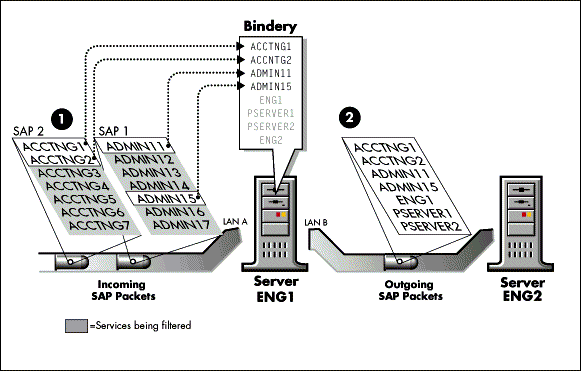
The IPX RIP/SAP filter can restrict inbound RIP and SAP traffic. Any network addresses and services removed inbound to the router are not placed in the network information database and service database, respectively (see Figure 14).
Because it is not possible to send packets through a router to a destination that is not included in the router's network address database, removing inbound network addresses deters users from accessing the filtered networks.
Figure 14: Sample traffic and bindery while doing inbound SAP filtering on server ENG1.
On a large internetwork, the amount of traffic generated by SAP broadcasts can become quite noticeable, especially on slower links. Additionally, large amounts of SAP information can pass to a file server from remote portions of the network that local users never (or rarely) access.
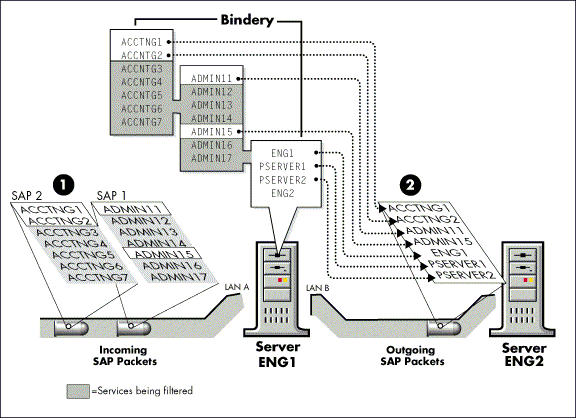
Outbound filtering on slow speed links can improve this situation. This restricts the amount of bandwidth used by service advertisements, but the router still has full visibility to all services. Therefore, the router can be used as a gatekeeper (see Figure 15).
Figure 15: Sample traffic and bindery while doing outbound SAP filtering on server ENG1.
Enabling IPX RIP/SAP Filtering
Use the following command to load the IPX RIP/SAP filter along with the SAPCFG.NLM configuration utility:
LOAD SAPCFG <Enter>
To load the IPX RIP/SAP filter without SAPCFG, use the following command:
LOAD SAHANDLE <Enter>
The filter enable switch in INETCFG enables loading of the IPX RIP/SAP filter NLM SAHANDLE. Use this switch to load the SAHANDLE IPX RIP/SAP filter NLM automatically whenever the NetWare MultiProtocol Router 2.1X or NetWare MultiProtocol Router Plus 2.1X software is started.
To automate the filter load sequence during the startup phase of the NetWare MultiProtocol Router 2.1x or NetWare Multi-Protocol Router Plus 2.1x software, complete the following procedures:
Load INETCFGat the server prompt.
Select Protocol Parameters.
Select IPX.
Select Route and Service Filtering.
Select Enabled.
Press <Esc< and select Yes to save your changes.
Press <Esc< twice to exit INETCFG.
SAP filtering can now be configured using SAPCFG, and is enabled each time the router is rebooted.
Disabling IPX RIP/SAP Filtering
To disable IPX RIP/SAP filtering, remove SAHANDLE from the system by entering the following command at the server prompt:
UNLOAD SAHANDLE <Enter>
If SAPCFG is loaded when you want to disable the IPX RIP/SAP filter, it must be unloaded before you unload the filter. The command sequence for unloading both SAPCFG and the IPX RIP/SAP filter is as follows:
UNLOAD SAPCFG <Enter>
UNLOAD SAHANDLE <Enter>
To disable SAP filtering permanently, disable it in INETCFG, using the same procedure as for enabling filtering, but select "Disabled" instead of "Enabled".
Using SAPCFG.NLM
Use SAPCFG.NLM to configure the IPX RIP/SAP filters. If a SAP filter database has already been created, SAPCFG allows you to read and modify the existing SAP filters. Using SAPCFG, you can remove any RIP or NetBIOS filters from the filter database.
To configure RIP and SAP filters, load SAPCFG using the following command:
LOAD SAPCFG <Enter>
Figure 16 shows the initial menu that is displayed on the screen.
Figure 16: The initial SAPCFG menu presents numerous configuration options.
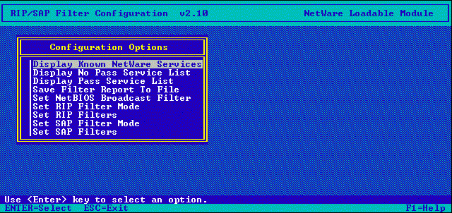
The bottom two lines of each SAPCFG display show command keys and context-sensitive "fast help." SAPCFG provides several function keys, as described in the following table.
Table 1: SAPCFG Function Keys.
|
Key
|
Function
|
|
<Enter> |
Views or modifiesthe selected option's configuration. |
|
<Ins< |
Adds a newconfiguration. Might bring up a list of items from which to select. |
|
<F3< |
Expands the definition of a service name containing a wildcard. The wildcard is represented by a "*" or "?" in the service name. The wildcard can be defined to represent a subset of allthe possible services that fit the wildcard description. |
|
<Del< |
Deletes or removes a configured option. |
|
<F5< |
Marks multiple entries for deletion. |
|
<Esc< |
Exits the currentconfiguration window and returns to the openingscreen and the command options. Press <Esc<from the main screen to exit the programand save configuration changes. |
|
<F1< |
Displays fullcontext-sensitive help while a menu or parameterscreen is displayed. It provides more comprehensivehelp about the currently selected menu optionor parameter line than the fast help linesappearing at the bottom of each SAPCFG display. |
The following table describes the RIP/SAP configuration options that can be set using SAPCFG.
Table 2: SAPCFG Configuration Options.
|
Option
|
Description
|
|
Display Known NetWare Services |
Displays theService Name, Service Type, and Status (Pass/NoPass) of all known servers. Any service thathas been filtered due to an inbound RIP filtersetting is unknown to the router and is not displayed. |
|
Display No Pass Service List |
Shows the ServiceName and Service Type of each service thatis configured for removal from outbound SAP packets. |
|
Display Pass Service List |
Shows the ServiceName and Service Type of each service thatis allowed in outbound SAP packets. |
|
Set NetBIOS Broadcast Filter |
Specifies whetherPacket Type 20 IPX packets (internetwork broadcasts) are filtered. |
|
Set RIP Filters |
Determineswhether networks are allowed to pass throughthe filter. Any RIP filter also removes theassociated services. The Set RIP Filter Modesetting determines whether entries that youconfigure specify networks to pass. Enter a list of network filters, indicating whetherthe filter is to be applied to inbound packets,outbound packets, or both. Each filter specification comprises a network numberand a network mask. The network mask specifieswhich bits of the network number are wildmatches. For each one bit in the networkmask, the corresponding network number bitmust exactly match the network number. Foreach zero bit in the network mask, the correspondingnetwork number bit can take any value. In addition to network filters, you can alsospecify network filter exclusions, an exceptionto the specified filter rules. An exclusioncan be used to allow one network number withina bank of network numbers that are beingfiltered out. |
|
Set RIP Filter Mode |
Determineswhether the RIP filters specified in theSet RIP Filters list indicate network numbersthat are allowed (Pass) or disallowed (NoPass) in RIP packets. In Pass mode, all networksnot specified by a RIP filter are removedfrom RIP packets. In No Pass mode, only thosenetworks specified by a RIP filter are removedfrom RIP packets. If the RIP Filter Mode is Pass and no RIP filters are defined, then all networks are filtered. If you want touse the filter in Pass mode for limitingoutbound traffic, define an inbound wildcardto allow all inbound networks. All networksfiltered inbound are also removed outbound. The Set RIP Filter Mode also affects operationof exclusions specified in the Set RIP Filterslist. When the RIP filter is in Pass mode,filter exclusions are removed from RIP packetseven though a RIP filter would allow thenetwork to remain in RIP packets. When theRIP filter is in No Pass mode, filter exclusionsare allowed in RIP packets even though aRIP filter would remove the network fromRIP packets. The behavior of RIP exclusionsis opposite to the behavior of RIP filters. The default setting of the Set RIP Filter Modeis No Pass. In this configuration, the routerallows all inbound and outbound networksin RIP packets. Configuration changes takeeffect immediately. |
|
Set SAP Filters |
Determineswhich services are allowed to pass throughthe filter. The Set SAP Filter Mode determineswhether the entries that you configure passservices. Accordingly, entries made in theSet SAP Filters list are added to the Passor No Pass lists. Enter a list of services,indicating a service type for each. Wildcardcharacters "*" and "?" can be used to defineService Names. Wildcards in the Service Typefield are converted by code into FFFF, whichmeans all types. A wildcard definitioncan be modified to include only a limitedlist of services (instead of all servicesthat match the wildcard name). When addinga new service to the list or modifying anexisting filter, all available Service Namesand Service Types are displayed. |
|
Set SAP Filter Mode |
Determineswhether the SAP filters specified in theSet SAP Filters list indicate Service Namesand Service Types that are allowed (Pass)or removed (No. Pass) from SAP packets. TheSAP filter can only operate in Pass or NoPass mode. In Pass mode, only servicesmatching the filters specified in the SetSAP Filters list are transmitted in SAP packetsby the router. All other services are filteredout. All Service Names and Service Typesmatching the SAP Filters Configuration listare displayed by the Display Pass ServiceList. All other Service Names and ServiceTypes known to the router can be displayedby the Display No Pass Service List. In No Pass mode, all services matching the filtersspecified in the Set SAP Filters list areremoved from transmitted SAP packets. The default configuration of the Set SAP FilterMode is Pass. In this configuration, therouter removes all outbound services fromSAP packets. Configuration changes take effectimmediately. |
|
Save FilterReport To File |
Saves the currentIPX RIP/SAP filter configuration to an ASCIItext file (RSFILTER.TXT) for printing, debugging,and historical reference. The file can onlybe viewed by using an ASCII text editor,or a word processor capable of reading ASCIItext. SAPCFG creates the RSFILTER.TXT filefrom the information stored in the configurationfile (FILTER.BIN). The FILTER.BIN file isa binary format file accessed by SAHANDLE.NLMto read the active filter specifications. Both the RSFILTER.TXT and the FILTER.BIN filesare located in the SYS:\ETC directory ofthe router. They can be accessed from thenetwork by attaching to the router and retrievingthe files through the network. |
Summary
As all aspects of network management increase in importance, SAP traffic is an area that can be managed rather easily. SAP management allows the network manager to reduce unnecessary network traffic. NetWare MultiProtocol Router provides the means to control and manage RIP and SAP traffic for improved performance on large internetworks.
* Originally published in Novell AppNotes
Disclaimer
The origin of this information may be internal or external to Novell. While Novell makes all reasonable efforts to verify this information, Novell does not make explicit or implied claims to its validity.