NetWare Link Services Protocol: Link-State Routing in a NetWare Environment
Articles and Tips: article
Manager of Software Development
NetWare Enterprise Products
JAY ISREAL
Vice President, Advanced Technology
Novell Corporate Technology
JOE GERVAIS
Product Marketing Engineer
NetWare Enterprise Products
SANDRA ORLANDO
Product Marketing-Communications
NetWare Enterprise Products
01 May 1994
This Application Note discusses the basics of NetWare Link Services Protocol routing, then gives guidelines on how networks of different sizes can be adapted to take advantage of this new internetworking technology. This information will help you prepare to implement NLSP on your Novell network.
- A New Approach to NetWare Internetworking
- NLSP: The Routing Solution for Global Internetworks
- Link-State Routing in a NetWare Environment
- Designing Networks for NLSP
- Conclusion
- Glossary of Related Terms
A New Approach to NetWare Internetworking
Just as Novell revolutionized local area networking, making it easier and less expensive to share information among different departments, Novell is now extending the benefits of NetWare beyond the LAN. New NetWare technology will let you build larger networks that are cost-effective and easy to install and maintain.
To help you build larger networks, Novell has developed a new routing protocol for NetWare networks - the NetWare Link Services Protocol (NLSP) - which promotes global internetworking by making NetWare networks more versatile, more scalable, and easier to manage. With NLSP, NetWare networks also use less bandwidth over local and remote connections. You can use NLSP to provide worldwide access to network services while distributing those services where they are most appropriate.
Along with the benefits of connecting dispersed and sometimes disparate LANs come several challenges:
Scalability: What networking equipment and protocols can handle everything from a single-building LAN to a global internetwork?
Manageability: How can you retain easy manageability when your internetwork may include tens of thousands of users all over the world?
Easy migration: How can you implement improved networking systems while maintaining full access for users on existing network segments?
Novell has designed NLSP to address all of these issues.
This document will help you prepare to implement NLSP on your Novell network. It discusses the basics of routing and of NLSP, then gives guidelines on how networks of different sizes can be adapted to take advantage of this new internetworking technology.
This in-depth discussion of NLSP will be helpful if you:
Have a network with more than one NetWare server
Want to connect NetWare servers across any combination of routers and WAN links
Want to connect your servers to another organization
NLSP: The Routing Solution for Global Internetworks
Novell's original routing protocol for NetWare networks, IPX RIP (Routing Information Protocol), and Novell's Service Advertising Protocol (SAP) were designed when internetworks were local and relatively small. Some of its characteristics are not ideal for large internetworks, especially on a worldwide level.
To overcome the limitations of RIP and its companion protocol SAP, Novell has developed the NetWare Link Services Protocol (NLSP). NLSP replaces RIP and SAP. It offers better performance, reliability, and management of NetWare traffic. Yet it retains compatibility with existing routers, enabling you to upgrade servers and routers on your network one at a time. Novell's own implementation of NLSP is offered as a NetWare Loadable Module (NLM). It will run on versions 3.11 and later of the NetWare network operating system, and will be included in future releases of NetWare MultiProtocol Router software.
NLSP Advantages
The NetWare Link Services Protocol offers the following benefits compared to RIP and SAP:
Improved routing
Reduced network overhead
Very low WAN overhead
Faster data transfer
Increased reliability
Less CPU usage
Better scalability
Superior manageability
Backwards compatibility
Support for multiple networking media
Optional manual link-cost assignment
Improved Routing. Routers based on RIP store summaries of routing information received from adjacent routers. These summaries show only the next hop for the router. In contrast, each NLSP-based router stores a complete map of the network. This enables NLSP-based routers to make more intelligent routing decisions than RIP-based routers. By sending packets along the most efficient route, NLSP saves time and bandwidth use. This should noticeably improve performance on complex internetworks.
Reduced Network Overhead. Each router using RIP periodically transmits packets containing its entire routing table. These broadcasts ensure that all the routers on the network have the same routing information. The broadcasts are made even when the routing information has not changed since the previous broadcast, so RIP routers generate a lot of traffic on the network. In contrast, NLSP only transmits routing information when something has changed. It also uses the more efficient multicasting method (only routers listening for the specified multicast packet address accept the routing information packet) instead of broadcasting (all devices on the LAN accept the packet).
Very Low WAN Overhead. Servers using SAP periodically broadcast their entire services database, taking up substantial LAN bandwidth and saturating low-speed WAN links.
NLSP provides a more efficient delivery mechanism for services information. It sends out updates only when services change. By eliminating SAP broadcast packets, NLSP can greatly improve performance on WANs (Figure 1). Also, NLSP's reliable delivery protocol eliminates the need for bandwith-wasting retransmissions.
Figure 1: Comparison of bandwidth consumption between RIP/SAP and NLSP.
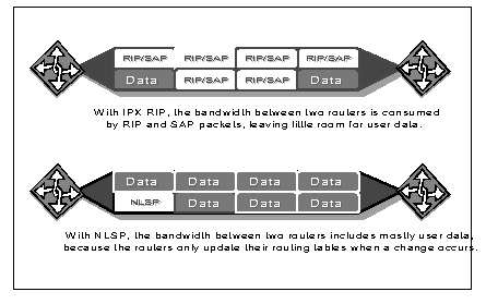
Faster Data Transfer. NLSP uses IPX header compression to reduce the size of data packets over a WAN link. In addition, NLSP reduces the size of the services data in the Link State Packets (LSP). This greatly reduces overhead traffic and allows more network bandwidth for actual data. The speedup in data transfer is especially noticeable across wide-area network links, which typically use lower-speed connections than do LANs.
NLSP also makes more efficient use of network resources by automatically load balancing across parallel paths. NLSP also supports load splitting. That is, if there are two or more equal-cost paths between two network nodes, the traffic is automatically divided among them to make more efficient use of the internetwork. You can place an upper limit on the number of paths used for routing, or even tell a router not to split the traffic load.
In addition, NLSP uses an efficient forwarding algorithm that enables routers to process incoming packets faster.
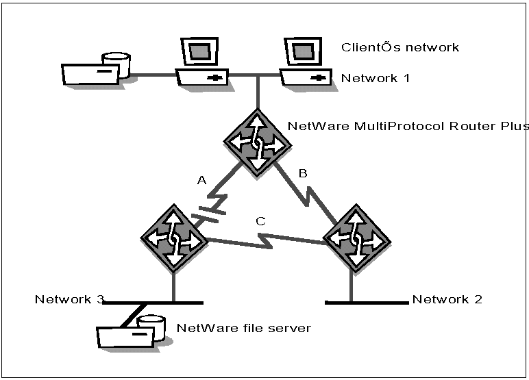
Increased Reliability. NLSP periodically checks links for connectivity and for the data integrity of the routing information. If a link fails, NLSP switches to an alternate link. It also quickly updates the network topology databases stored in each node when there are connectivity changes anywhere in the routing area. This ensures that all routers can continue to select the best routing options.
Figure 2 shows how NLSP routes around failed links. The primary path from clients on Network 1 to NetWare services on Network 3 is route A because it is the shortest path option among the three routes. When the link A fails, the traffic is automatically rerouted to the path over links B and C. When link A is restored, traffic automatically resumes on link A.
Figure 2: NLSP quickly reroutes traffic around failed links.
Less CPU Usage. In most networks, converting from RIP to NLSP will decrease the computer time needed for routing because NLSP does not require periodic routing updates. In RIP and SAP networks, processing these updates takes a lot of CPU time.
As with any link-state protocol, NLSP does take more time than distance-vector protocols to calculate the best routes for packets. However, this extra overhead is small in actual practice. Once you have migrated sections of your internetwork to NLSP, you should notice the increase in routing efficiency over your RIP network.
Better Scalability (Support for Larger Networks). Packets relayed by RIP routers could go through no more than 15 hops between their source and destination; NLSP can support up to 127 hops.
Also, NLSP permits hierarchical addressing of network nodes, letting you deploy networks containing thousands of LANs and servers.
NLSP provides quick convergence of routing information which allows routers to report network changes and reroute traffic to the best available path faster than with RIP.
Superior Manageability. NLSP has a standardized management interface. Any management console on your Novell network that uses the Simple Network Management Protocol (SNMP) such as the NetWare Management System (NMS ) can monitor and control the operation of an NLSP router (or a RIP/SAP router implemented to the NLSP specification). SNMP can run over the IPX, IP, AppleTalk, and OSI protocols. A system administrator can derive a map of the entire NetWare internetwork from a single NLSP router.
The Management Information Base (MIB) implementation for NLSP allows you to observe network topology changes in real time, enabling you to isolate trouble spots and solve problems before they impact your entire network.
Backward Compatibility. Any combination of NLSP-based and RIP-based routers can be used in the same internetwork. You can migrate LAN segments from RIP to NLSP as needed; you do not need to upgrade the entire network at the same time. NLSP software was designed to let you migrate NetWare servers and routers without rebooting them.
Support for Multiple Networking Media. NLSP implements end-to-end delivery of data traffic over internetworks of heterogeneous media such as Ethernet, token-ring, and point-to-point links. Novell's implementation of NLSP can operate over all media supported by NetWare servers, with the same drivers and network interface cards.
Optional Manual Link-Cost Assignment. NLSP routers know the cost of every link and automatically choose the most efficient path for each packet. A manual override allows network managers to modify the cost of a given route. For example, you may want to make a server/router more costly than a dedicated router. In normal circumstances, NLSP uses the dedicated router; if that device fails or is brought down for maintenance, traffic is rerouted through the server/router.
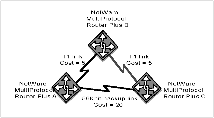
Another application for this feature is to use manual link-cost assignment to configure a backup link over a WAN (Figure 3). In an IPX RIP network, RIP chooses the path with the fewest hops; in Figure 3, that is between Router A and Router C over the slower WAN link. NLSP enables you to manually assign costs to the links and route traffic based on those costs. In this example, traffic could be configured to pass through Routers B and C over fast T1 lines, with the 56-Kbps line used only as a backup link.
Figure 3: Manual link-cost assignment routes traffic more efficiently.
Third-Party NLSP Compatibility
Novell is committed to making its systems open and interoperable with other vendors' products. We have made the NLSP specifications available to router vendors and other third-party developers so that they can implement it in their products for compatibility with NetWare networks.
We also offer developers technical support, interoperability testing, and certification. The certification program will ensure that third-party NLSP implementations work in large IPX networks. This program will be added to the current IPX router certification program.
Because NLSP is based on the Open Systems Interconnection Intermediate-system to Intermediate-system (OSI IS-IS) protocol, the many vendors who already offer an IS-IS protocol stack can adapt it to support NLSP.
Link-State Routing in a NetWare Environment
In order to understand why NLSP was developed, it is first necessary to understand the basics of why routing is needed and how it works. This section opens with a brief discussion of routing and routing protocols, then explains the relationship between Novell's current and future routing protocols.
Network Routing
Routing is the process of forwarding data between different networks or network segments. If there were no routers, users would have to explicitly tell each data packet how to get to its destination.
Routers - the software programs that perform routing - operate at the Network layer of the OSI model (Figure 4). They exchange information with each other about the topology of the network so that each router can make good routing decisions.
Figure 4: The relationship of Novell's routing protocols to the OSI internetworking model.
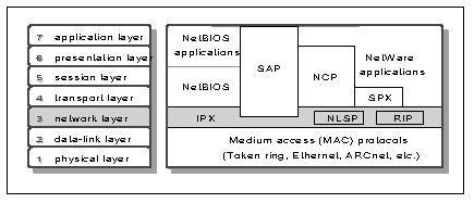
Note: The NetWare environment includes additional protocols; only those relevant to IPX routing are shown here.
The function of the Network layer is to provide end-to-end delivery of information over an internetwork of diverse data-link media, such as Ethernet and token ring. The Network layer hides the details of the data links from applications and network services that run on top of it. The different segments of the internetwork between any two end nodes must use the same Network-layer protocols.
Novell's Network-layer protocol is IPX. Within it, the routing protocol currently used is RIP, and the service advertising protocol is SAP. NLSP provides an alternative to both of these protocols. NLSP packets can contain both IPX networks and services.
Distance-Vector Routing Protocols
Traditionally, routers have communicated using distance-vector routing protocols. In an internetwork based on a distance-vector routing protocol, routers typically exchange information about the network's topology through periodic broadcasts with their immediate neighbors. Each node then consolidates the information it has received and passes the summarized data along to other routers, servers, and end nodes (such as printers and workstations).
Examples of distance-vector routing protocols include IPX RIP in the IPX protocol suite, IP RIP and Cisco IGRP in the IP protocol suite, and RTMP in the AppleTalk suite (Figure 5).
Figure 5: Common distance-vector and link-state routing protocols.

NLSP and Other Link-State Routing Protocols
More recently, link-state routing protocols have been developed to address the demands of large internetworks. Link-state protocols scale more readily than distance-vector protocols to handle large, complex internetworks, and they can adapt more quickly to network topology changes.
In an internetwork that uses a link-state routing protocol, each router or server typically floods information about itself and its immediate neighbors to every reachable router in a routing area. (A routing area is a subset of the routers in an entire internetwork. They are created to enhance scalability, manageability and security.) Such transmissions are made only when something has changed, so link-state networks are less burdened by unnecessary repetitive traffic.
Each router uses the information it receives to build its own map of the routing area, rather than relying on secondhand summaries as do distance-vector routers. The map includes the area's routers and servers, the links connecting them, the operational status of the routers and links, and related parameters. (Workstations find out about available network services through the map maintained by their nearest router.) Because the routers keep track of the status of other routers and links, such a protocol is described as link state.
Examples of link-state protocols include the Open Shortest Path First (OSPF) protocol in the TCP/IP protocol suite, the IS-IS protocol in the OSI suite, and NLSP in the IPX suite (see Figure 5).
Different link-state and distance-vector protocols can coexist on the same NetWare internetwork and even in the same multiprotocol router.
NLSP, RIP, and SAP
Novell NetWare has historically used two protocols to propagate network information:
IPX RIP is a distance-vector protocol that is used to convey routing information. It is modeled after the Xerox protocol of the same name. Versions of RIP are also used with the IP and AppleTalk protocols.
SAP is used to distribute information about available network services such as file servers and printers.
|
The Role of SAP SAP is pervasive in current networks based on NetWare3.11 and earlier. The need for it has been reduced with the introductionof NetWare Directory Services (NDS) in NetWare 4 because workstationscan now locate network services by consulting an NDS server. SAPis no longer needed to propagate services information around thenetwork. However, SAP will continue to play a role in IPXnetworks because many networks have older NetWare compatible devicesthat require it. In an NLSP and NDS network, SAP is still usedby workstations when they start up to query their local NetWareserver or router about the location of the nearest NDS server.Once that has been determined, the workstation and the NDS serveruse NDS protocols to communicate directly with each other; thesame is true between Directory servers. |
Both RIP and SAP send their information to the entire network periodically (typically once a minute). This allows other nodes to quickly discover which routers and services are available, but it also burdens the network with frequent broadcast messages.
With the advent of NLSP, you can maximize the efficiency of your NetWare network by using NLSP for all communications among routers and servers. However, RIP and SAP will still be included with NetWare software for compatibility with Novell and third-party network devices that have not been upgraded to NLSP, and for communications between routers and workstations.
Internetworks can contain both RIP/SAP and NLSP routers. This compatibility allows you to upgrade your network at your own pace. NLSP can automatically detect the presence of non-NLSP routers and servers, and generate the periodic RIP and SAP broadcasts they expect to see. Such broadcasts are restricted to the network segments containing those nodes, preventing the rest of the internetwork from being flooded with the high traffic load seen when RIP and SAP are used.
Designing Networks for NLSP
You can start preparing now for the benefits that NLSP can bring to your Novell network. Careful analysis of your existing network will show where you may need to change addresses, names, and configurations so that all components can be integrated smoothly into an NLSP-based internetwork.
Physical Network Configuration
NLSP gives you more network configuration choices than RIP-in particular, NLSP makes mesh configurations practical. Mesh networks provide much higher reilability than backbone (including collapsed backbone) or tree-structured networks because each node has more communications links connected to it (Figure 6).
Figure 6: Collapsed backbone and mesh networks.
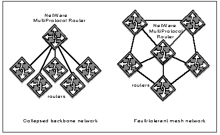
The failure of a single link will not impede traffic flow to and from that node. However, broadcast traffic in a mesh network using RIP and SAP can quickly overwhelm the network's bandwidth. For this reason, many network designers have chosen to use a backbone or tree-like configuration despite their greater susceptibility to problems.
Because NLSP can synchronize routing databases quickly after a topology change, and because it generates far less overhead traffic than RIP and SAP, it makes mesh networks much more feasible. As part of your preparations for implementing NLSP, you will probably want to determine whether to migrate your network to a mesh design so that you can benefit from its higher reliability.
Hierarchical Routing
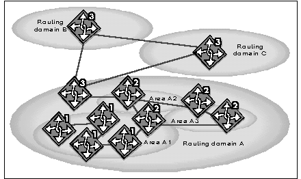
NLSP is designed to be used in an hierarchical routing environment, where routing areas can be linked together into routing domains and domains can be linked to create a global internetwork (Figure 7).
Figure 7: Hierarchical routing.
|
Key Terms area. A collection of connected networks all having the same area address. area address. The network address and mask in a routing area. domain. A part of the routing hierarchy. Level 1 routing. The interaction of routers within the same area. Level 2 routing. Routing between areas to form a routing domain controlled by a single administrative entity - for example, communications within an organization. Level 3 routing. Routingbetween routing domains controlled by different administrativeentities - for example, communications between different companies. Link State packet (LSP). A packet generated by a router in a link-state routing protocolwhich lists that router's neighbors and attached networks. routing area. A subset of routers in an entire internetwork. routing domain. A collection of areas joined by Level 2 routers. |
Level 1 routers are used to connect network segments within a given routing area. Areas are connected to each other by Level 2 routers; domains are connected by Level 3 routers. A Level 2 router also acts as a Level 1 router within its own area; likewise, a Level 3 router also acts as a Level 2 router within its own domain.
The second level of routing simplifies the process of enlarging a network by reducing the amount of information that every router must store and process to route packets within a domain. Instead of storing link-state information for every router and network segment in its domain, a Level 1 router keeps this level of detail only for its own area. To exchange traffic with other areas, it need only find the nearest Level 2 router.
Between areas, Level 2 routers only advertise the area address(es) for their respective areas, not their entire link-state databases. Similar economies are achieved by Level 3 routers for routing between domains. This is typical of the way in which hierarchical routing can reduce information storage and processing requirements.
With hierarchical routing, each independent organization can be a separate domain. This could be a company, a university, or an agency. It could also be a public carrier connecting organizations with each other. Within a routing domain, each local campus (or other suborganization having its own administrative staff) can constitute a separate routing area.
The first release of the NLSP specification covers Level 1 routing and routing to the nearest Level 2 router. Level 2 and Level 3 routing specifications will be available in the future. Network administrators should plan ahead now for hierarchical routing in their NetWare networks.
Addressing for Hierarchical Routing
Networks that use hierarchical routing mandate certain addressing and naming requirements for their components. These requirements ensure that when a LAN or an individual network device (such as a router, server, workstation, or printer) is added to the internetwork, it will not have an address or name that conflicts with any other node. Here is some information on how NLSP deals with addressing at various levels of an internetwork.
Address Assignment Within an Area or Domain. In IPX, a 32-bit network number is assigned to each LAN segment. NetWare 3 and NetWare 4 servers also have "internal" network numbers.
Each routing area is identified by two 32-bit quantities: a network address and a mask. The pair of numbers is called an area address.
In hexadecimal notation, an example of this might be:
01234500
FFFFFF00
The first number (1234500) is the network address for this routing area. The second number (the mask) indicates how much of the network address identifies the area itself and how much identifies individual networks within the area.
In the example above, the first 24 bits of the address (012345) identify the routing area. Every network number within that area starts with the identification 012345. The remaining eight bits are available to identify individual network numbers within the routing area; examples could include 01234500, 012345AB, 012345C3, and so on.
A routing area can have as many as three different area addresses, and each address can have a different mask. NLSP treats multiple addresses as synonymous identifiers of the same routing area. The purpose of having more than one address is to allow the routing area to be reorganized without interrupting operations.
For example, to split a routing area in half, you would introduce the new area address into half the routers, one by one. Then you would remove the old address from those routers, one by one. As long as one router has both addresses, there is one routing area. As soon as all the routers have separate area addresses, there are two areas.
Any combination of area addresses can be used within a domain.
Address Assignment Across Domains. Cross-domain routing is more efficient if all the area addresses in a given domain share a common prefix, for the following reasons:
The data shared among domains is more compact because addresses can be expressed by the common prefix instead of requiring the full area addresses. This results in lower consumption of network bandwidth and storage capacity.
As a consequence of this condensed addressing, Level 3 routers have less data from other domains to process-and so have less work to do-when they make routing decisions. This saves computing cycles.
Because there is no need to propagate full area addresses to other domains, organizations can hide their internal network topology from outsiders. This can significantly benefit an organization's security.
For all of these reasons, those planning address assignments should consider using hierarchical addresses even though such addresses are not required for correct operation of an NLSP-based network.
For example, if addresses in an internetwork are assigned hierarchically, the Level 3 router in Domain A might have the address list shown in Figure 8.
Figure 8: The use of common prefixes for all area addresses within a given domain streamlines cross-domain communications. addresses within a given domain streamlines cross-domain communications."

Note that the area addresses used within each domain differ in the fifth hexadecimal digit: "1" for Domain A, "2" for B, and "3" for C. The Level 3 router for Domain A only needs to remember that all addresses in Domain B begin with "CCCC2"; it then forwards to Domain B any packet whose destination address begins with that prefix. Domain A's router does not have to maintain a complete list of valid Domain B area addresses or network numbers. Similarly, the Level 3 routers in Domains B and C see all of Domain A represented by the prefix "CCCC1".
Assigning Addresses
With the initial release of NLSP, the default area address suffices for many situations. All routers reachable by NLSP from a given NLSP router will be in the same routing area. (An exception is a large internetwork in which two or more areas share a LAN. See Figure 11 and the discussion surrounding it.)
Despite this initial universality, we recommend that you use foresight when assigning individual IPX network numbers to network segments and to the "internal" networks of routers and servers. If you ever expect to divide your network into separate areas, you will need to ensure that all IPX network numbers intended for a certain area are in the same area before you start configuring area addresses. For example, a network intended to become part of Area 1 in Figure 9 would need to have an address in the range CCCC15xx.
We suggest that you subdivide your total available address range into smaller ranges by geography, because each geographical location can then easily become a separate routing area when hierarchical addressing is introduced. It also helps to subdivide ranges to match the delegation of administrative responsibility. Giving each divisional or departmental administrator his or her own subrange of network addresses reduces the demands on top-level network administrators.
With large internetworks, it is sometimes useful to have two levels of address ranges, partitioned hierarchically by geography (areas and domains). With hierarchical routing, geographical address partitions make operation more efficient by allowing the routing information exchanged between areas to be aggregated.
To determine a beginning address range, you may want to contact the Novell Network Registry. This is an optional service having worldwide coverage. Its role is to ensure name and address uniqueness for those who participate by keeping a permanent record of assigned IPX address ranges and top-level NetWare organization names. This will facilitate joining departmental networks into an enterprise-wide internetwork, and enabling different organizations to communicate with each other.
Note: For more information, contact Novell by calling (408) 577-7506, or send Internet e-mail to registry@novell.com or MHS NHUB e-mail to registry@novell.
Migrating from RIP to NLSP
Novell has created a smooth migration path from RIP to NLSP. Routers and servers can be upgraded by installing NLSP one system at a time, without disrupting the rest of the network. Segments converted to NLSP will immediately see the benefits of reduced overhead traffic, especially across WANs. No modifications are required to client software, such as NetWare requesters or client IPX protocol stacks.
Novell is making NLSP software available for NetWare servers based on NetWare 3.11 or later. (To run NLSP on a NetWare 2 server, you will first need to upgrade it to at least NetWare 3.11. To run NLSP on any router built with ROUTEGEN, you will first need to upgrade to NetWare MultiProtocol Router.) Future releases of the NetWare MultiProtocol Router and MultiProtocol Router Plus will also support NLSP.
The exact procedures for migrating your Novell internetwork from RIP to NLSP will vary depending on the size of your internetwork-specifically, how many IPX network numbers there are. This will be the number of physical IPX networks plus internal IPX network numbers. You can determine the total number by using the "Display Networks" command at a NetWare console. There are no rigid rules for the best way to migrate, but some guidelines are provided below.
General Guidelines. It is usually best to start your migration in one location and migrate one network at a time. You should see improvements on each network segment as soon as you replace RIP with NLSP. This also applies to WANs: converting both ends of the WAN link from RIP to NLSP should provide an immediate improvement in network response over the WAN link.
Small Internetworks. An internetwork can be fairly complex and still be treated as a single routing area. If your internetwork has:
Fewer than 100 network numbers, or
Between 100 and 400 network numbers but no loops among routers
treat it as one routing area and install NLSP on all routers. Systems can be upgraded to NLSP in any order.
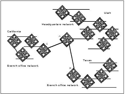
Figure 9 shows one routing area containing a headquarters network and branch-office networks.
Figure 9: Small internetworks can be treated as a single routing area.
Medium-Sized Internetworks. If your internetwork has:
Between about 100 and 400 network numbers, and
There are loops among routers,
you can still treat it as one routing area, but the migration will be different from that used for small internetworks. First, install NLSP starting at the central core WAN infrastructure, then proceed outward from the WAN routers in each local campus.
Figure 10 shows an example internetwork treated as a single routing area.
Figure 10: Medium-sized internetworks can also be treated as a single routing area, but systems should be migrated in a specified order. as a single routing area, but systems should be migrated in a specified order."
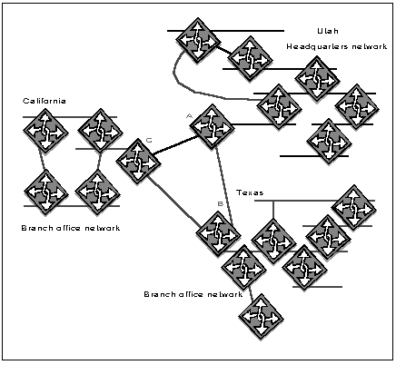
Install NLSP first in WAN routers A, B, and C. Those three will then be using NLSP among themselves, while RIP runs throughout each campus. Then, within each campus, move outward from the NLSP router, installing the new software in adjacent routers one by one. Some RIP routers can remain, since NLSP includes RIP compatibility. Caution should be used when converting loops, with the preference being to convert the entire loop at once.
Large Internetworks. Internetworks of more than 400 network numbers should be partitioned into areas. With hierarchical routing these will become NLSP routing areas joined by Level 2 routers, but initially RIP segments can be used to link two NLSP areas.
There are no hard and fast rules about area size. Typically, useful areas hold up to 400 network numbers. More important than adhering rigidly to a particular size is that the area boundaries be aligned with the natural geographical boundaries of the internetwork. If an organization has several campuses or branch offices, a logical approach is to make each one a separate area. A large campus may need several areas.
It is preferable for LANs to be the area boundaries, and for the long-haul WAN infrastructure to be an area of its own. In Figure 10, for example, there would be four areas: one for each state and one for the WAN triangle. To see how this works, look at Figure 11, which enlarges router B from Figure 10 and the LAN to which it is attached.
Figure 11: A close-up of the boundary between two areas in a large internetwork. The same principle applies between two domains. boundary between two areas in a large internetwork.
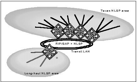
One LAN- called a "transit LAN" - contains the boundary between the Texas area and the long-haul area. In Figure 11, this transit LAN is an FDDI ring. Routers on the Texas side of the transit LAN are called "feeder routers" because they feed data from numerous Texas networks (LANs and WANs) into the long-haul area. The feeder routers talk NLSP among themselves and with other Texas routers.
Likewise, Router B talks NLSP to its long-haul peers, A and C. But B communicates with the its local feeder routers using RIP and SAP.
RIP and SAP filtering between the two areas can be used to economize on the information transmitted between the three states and the amount of out-of-state information blanketed over a state's area.
Variations on the Basic Migration Techniques. Although the methods above are useful as basic approaches, there are variations that can work better in specific circumstances. Here are two variations:
Your internetwork may include third-party routers which do not support NLSP. If, however, they support IP, you can take advantage of the new IP Relay protocol included in the NLSP specification. IP Relay allows IPX traffic to flow efficiently through regions of IP routers to reach peer IPX routers. It uses a streamlined type of virtual-circuit operation. Either NLSP or RIP canoperate over an IP Relay virtual circuit.
The portion of your internetwork in a given geographic area maybe too large for a single NLSP area. One way to handle this situationis to use a different protocol on the transit LAN. This effectively subdivides the single geographic area into several areas.
In Figure 11, for example, the feeder routers can all communicate with each other using RIP and SAP. There is no need for NLSP on the transit LAN. Each feeder router is in a separate NLSP area, and is a contact point between Texas areasBas well as from Texas to the long-haul area.
RIP and SAP Filtering
Prior to NLSP, RIP and SAP filtering was used in networks for two purposes: to limit connectivity (such as restricting access to servers in the finance department) and to reduce the amount of routing and service information that was propagated through the network.
With NLSPs increased efficiency, filtering for purposes other than security is not necessary within a routing area. As mentioned in the section on migrating large internetworks, filtering can still be done on the RIP/SAP transit LAN.
To provide NLSP filtering for security purposes, Novell is implementing packet filtering for IPX. Packet filtering is based on a combination of source and destination addresses, so it offers more flexible control than all-inclusive filters between departments.
Conclusion
NLSP is just one of Novell's recent technological innovations that make it practical to build larger, more richly connected, farther-reaching internetworks. Network computing no longer need be confined to a workgroup. More and more organizations are connecting NetWare users on departmental, enterprise, and even inter-organizational internetworks. The result is that users can reach farther for the resources they need to do their jobs efficiently and effectively. In turn, this gives organizations more power to build comprehensive, reliable information systems.
Glossary of Related Terms
administrative entity. A group of nodes administered in common and sharing a common routing strategy.
area. A collection of connected networks all having the same area address.
area address. The network address and mask in a routing area.
cost. A metric assigned to a circuit that determines the likelihood of traffic being routed over that circuit.
Data-Link layer. Second layer of the Open Systems Interconnection (OSI) model; it is involved in both packaging and addressing information and controlling the flow of separate transmissions over communications lines.
distance-vector protocol. A protocol that derives best path information from the best path information present in adjacent nodes. IP RIP and IPX RIP are examples of distance-vector protocols. domain. In NLSP, a part of the routing hierarchy. On the Internet, a part of a naming hierarchy. Syntactically, an Internet domain name consists of a sequence of names separated by periods. In OSI, it is generally used as an administrative partition of a distributed system.
FDDI (Fiber Distributed Data Interface). ANSI standard for high-speed (100 Mbps) fiber-optic connections.
hierarchical addressing. An addressing scheme whereby a network is partitioned into sections, with the section identifier forming one part of each destinations address, and the destination identifier forming another. This allows destination identifiers (such as server names) to be reused in different sections, because the section identifier distinguishes them. There can be more than one level of section.
IP Internet Protocol. TCP/IP protocol that provides datagram delivery of messages.
IPX Internetwork Packet Exchange. NetWare protocol similar to the Xerox Network Systems (XNS) protocol, providing datagram delivery of messages.
IPX address. An IPX address contains a four-byte network number, a six-byte node number, and a two-byte socket number.
Level 1 routing. The interaction of routers within the same area.
Level 2 routing. Routing between areas to form a routing domain controlled by a single administrative entity (for example, communications) within an organization.
Level 3 routing. Routing between routing domains controlled by different administrative entities, for example, communications between different companies.
Link State packet (LSP). A packet generated by a router in a link-state routing protocol which lists that routers neighbors and attached networks.
link-state protocol. A protocol in which each router floods information on the state of its links to all nodes in the internetwork. This approach reduces routing loops and network traffic.
multicasting. A transmission method where only those devices listening for a specified multicast packet address accept the routing information packet.
NetWare Link Services Protocol (NLSP). IPX link-state protocol used by IPX routers to share information about their routes with other devices on the network.
network address. Network-layer address that refers to a logical network device. Also known as a protocol address.
Network layer. Third layer of the OSI model; Network-layer protocols send information over several hops to its destination and manage the differences between network media so that higher-layer protocols need not account for the distinctions.
routed protocol. Protocol than can be routed by a router. IPX, IP, AppleTalk, and OSI are examples of routed protocols.
router. A device that connects two or more networks using the same networking protocol. Routers operate at the Network layer (Layer 3) of the OSI model for forwarding decisions.
routing area. A subset of routers in an entire internetwork.
routing domain. A collection of areas joined by Level 2 routers.
Routing Information Protocol (RIP). Distance-vector protocol that provides a measure of distance, or hops, from a transmitting workstation to a receiving workstation.
routing protocol. Protocol that enables routing through the implementation of a specific routing algorithm (for example, RIP, OSPF, NLSP, and IS-IS).
routing table. Table stored in a router that keeps track of routes (and in some cases, metrics associated with those routes) to a particular network destination.
Service Advertising Protocol (SAP). Responsible for disseminating services information to all nodes in an IPX network.
Simple Network Management Protocol (SNMP). Network management protocol used with various networking protocols, including IPX and IP.
* Originally published in Novell AppNotes
Disclaimer
The origin of this information may be internal or external to Novell. While Novell makes all reasonable efforts to verify this information, Novell does not make explicit or implied claims to its validity.