Optimizing NetWare Wide Area Networks
Articles and Tips: article
Product Marketing Engineer
NetWare Enterprise Products
01 May 1994
This Application Note describes several techniques to reduce line overhead and increase data capacity on wide area circuits.
Introduction
For more than a decade, the NetWare operating system has been used to connect workgroups and departments in a local area network (LAN). As computing resources have become more distributed, Novell products have been used to link the entire enterprise, enabling users at branch offices to share resources with headquarters networks.
This migration from centralized local networks to distributed wide area networks (WANs) poses new challenges for network managers that want to optimize network performance. For instance, on a LAN optimization is less of an issue because bandwidth is inexpensive and latency is minimal. On a WAN, performance optimization is more critical because WAN media uses slower transmission speeds and has higher latency than LAN media.
This Application Note will help you optimize the performance of your wide area links by explaining a variety of WAN optimization techniques. This article assumes that you have a basic understanding of routing and wide area networking.
WAN Circuit Components
While LAN performance is measured in packets per second, WAN performance is more accurately measured in the amount of throughput on a link. To optimize performance on a WAN, you need to optimize the WAN circuit.
WAN circuits include two components: line overhead and payload capacity (see Figure 1).
Figure 1: WAN pipe.
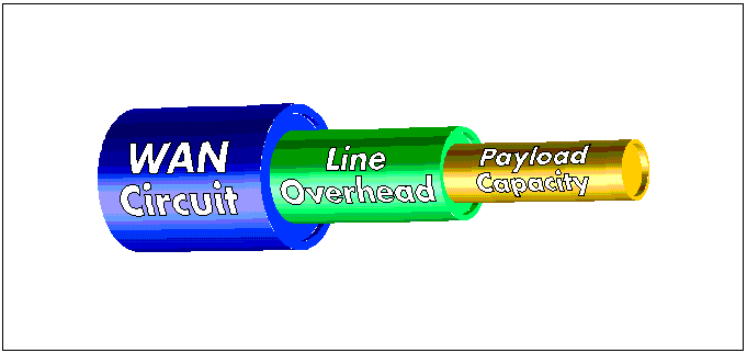
Line Overhead. Line overhead contains the media's framing, routing protocol, and network layer protocol overhead. Line overhead is similar to the build-up that occurs inside a plumbing pipe, restricting the capacity of the system. To increase a circuit's capacity, you must minimize line overhead.
Reducing line overhead in a multiprotocol environment is critical, because it increases circuit capacity for all protocols, not just the protocol being tuned. For example, reducing Service Advertising Protocol (SAP) overhead increases the available bandwidth for IPX, IP, and AppleTalk clients.
Payload Capacity. Payload capacity is the speed at which data moves through a circuit. You can overcome transport protocol inefficiencies and increase capacity of a circuit through by using data compression.
General Guidelines
To determine which areas of your network will benefit from a reduction in line overhead and which areas will benefit from a reduction in payload, review the following guidelines:
Payload maximization is your goal in very large networks (over 4,000 network segments and services) that use only IPX and T1(1.544 Mbps) connections. These networks have minimal line overhead-for example, under five percent of network capacity is associated with in band maintenance traffic. You will not see significant bandwidth improvements in this scenario.
You will see substantial reductions in line overhead in the following scenario. Large networks (1,000 network segments and services) that have small sites and branch offices connected by 64 Kbps or slower circuits can have line overhead at 25 percent or more of circuit capacity. In this scenario, reducing line overhead is critical. Without optimization of line overhead, circuits will be saturated, and payload optimization will produce minimal results.
Optimizing WAN Circuits
By optimizing both the line overhead and the payload capacity, you can dramatically improve network throughput and transmit more user data over wide area connections. This section covers the following areas of optimization.
Line optimization:
Header Compression
PPP Data Compression
RIP and SAP Filtering
NetWare Link Services Protocol (NLSP)
NetWare Directory Services (NDS)
Static Routing
Payload optimization:
PPP Data Compression
Packet Burst and LIP
Header Compression
Header compression is a method used to reduce data link or network layer header overhead. Data link header compression reduces the size of a header at the data link layer. Network layer header compression reduces the size of the header at the network layer.
Data-Link Header Compression. Data-link header compression is only available for the Point-to-Point Protocol (PPP) because packet switching does not occur over the WAN. Other media, such as Frame Relay and X.25, do not offer header compression because the infrastructure is not as easy to manipulate as PPP. For header compression to be effective on X.25 and Frame Relay, all intermediate switches must implement header compression. This would require changes in a service provider's infrastructure on a regional, national, and global basis.
PPP Header Compression. With header compression, PPP has the option of eliminating the leading byte of the protocol field in the header when it is not used, reducing this field from two bytes to one. The PPP specification also allows the address and control field of the data-link layer to be eliminated because the high-level data-link control (HDLC) fields always contain the static values of 0xFF (all stations address) and 0x03 (unnumbered information). Eliminating these fields reduces the PPP data-link header by another two bytes.
Note: The HDLC address and control fields cannot be eliminated if you are using PPP Data Compression because the compression control protocol uses LAPB to provide reliable delivery of compressed data. LAPB dynamically uses both the address and control fields. In addition, the PPP protocol field is always two bytes for a compressed frame, so it cannot be compressed either.
PPP header compression can be used on either uncompressed lines, or lines with hardware data compression such as dial-up lines with modems supporting V.42 bis or Microcom Networking Protocol (MNP).
Network-layer Header Compression. Network-layer protocol header compression works with a variety of WAN media. It can be deployed on a selective basis because the uncompressed network-layer header is restored upon receipt by each router. This enables you to compress only over those WAN interfaces that would benefit the most from optimization. In addition, each intermediate switching node in an X.25 and Frame Relay network does not have to implement header compression because network-layer header compression only impacts the two routing nodes at the end of a WAN circuit. It does not affect any of the switching fabric used for the WAN media.
Network-layer header compression supports all WAN media including PPP, X.25, Frame Relay, and Integrated Services Digital Network (ISDN). This type of compression is best for line speeds of 64 Kbps or below because it takes less processing time for the router to compress and decompress the header than to send the full header. Higher speed lines, on the other hand, require more processing time, and will not offer the throughput improvements you will see on lower speed links.
There are two common network layer header compression algorithms: Van Jacobson IP Header Compression for the TCP/IP protocol, and compressed IPX for the IPX protocol.
TCP/IP Header Compression. Van Jacobson published Compressing TCP/IP Headers for Low Speed Serial Links as a Request for Comment (RFC) 1144. This method of header compression reduces the TCP/IP header from 40 bytes (Figure 2) to between three and five bytes (Figure 3). Compression begins by caching the first header of a TCP/IP conversation, and then sending the incremental changes for all future packets using that compression slot.
Figure 2: TELNET packet without compression - 41 bytes.
|
45 |
Version, HeaderLength |
|||
|
00 |
Class of Service |
|||
|
00 |
29 |
Length: |
||
|
00 |
D2 |
Identification |
||
|
00 |
00 |
Fragmentation Flags, Offset |
||
|
3C |
Time to Live |
|||
|
06 |
Protocol |
|||
|
C7 |
B2 |
Checksum |
||
|
82 |
39 |
AC |
69 |
Source IP Address |
|
82 |
39 |
05 |
6F |
Destination IP Address |
|
04 |
04 |
Source Port |
||
|
00 |
17 |
Destination Port |
||
|
00 |
0A |
9B |
2C |
Sequence Number |
|
3D |
E8 |
A3 |
01 |
Acknowledgment Number |
|
50 |
Header Length |
|||
|
18 |
Control Bits: 24 |
|||
|
0B |
40 |
Window: 2880 |
||
|
09 |
05 |
Checksum: 0x0905 (Valid) |
||
|
00 |
00 |
Urgent Pointer |
||
|
65 |
Data |
Figure 3: TELNET packet with compression-4 bytes.
|
0B |
Compression Flags |
|
|
09 |
05 |
Checksum |
|
65 |
Data |
Van Jacobson compression was designed to reduce TCP/IP header overhead so that TELNET could effectively run at speeds less than 4,800 bps. To meet this goal, character echo must occur in less than 200 ms - which is a challenge because of the 40-byte header for a single-character payload. Without Van Jacobson compression, the line speed must be at least 4,000 bps to handle these 82 bytes in 200 ms.
In addition to TELNET traffic, the lines between routers also handle file transfers and interactive traffic. Even with priority queuing, a TELNET packet may have to wait for a File Transfer Protocol (FTP) packet to finish transmission. However, the FTP data packet must equal 10 to 20 times the header size of a TCP/IP packet to ensure reasonable line efficiency. For example, a line's maximum transmission unit (MTU) should be at least 500 to 1000 bytes for a 40-byte TCP/IP header to reduce line overhead to five to ten percent of line capacity. This allows you to achieve 90 to 95 percent line utilization.
The compressed three byte header makes these character echo times possible. In addition, the compression of FTP headers improves TELNET performance by reducing the MTU while obtaining 90 percent line utilization for FTP traffic.
User Datagram Protocol (UDP) and other IP traffic cannot take advantage of Van Jacobson compression because the protocol does not specify a method to only compress the IP header.
IPX Header Compression. Telebit Corporation extended the Van Jacobson algorithm to the IPX protocol. They published RFC 1533C Compressing IPX headers over WAN media. This specification shows how to compress any IPX header. It also gives you the option of compressing the transport header of NetWare Core Protocol (NCP) type 2222 (NCP Request) and type 3333 (NCP Reply) packets.
IPX header compression reduces the header from 30 bytes to one byte in a best case scenario, or to seven bytes in the worst case. NCP header compression reduces IPX and NCP overhead from 37 bytes (Figure 4) to two bytes in the best case or eight bytes in the worst case (Figure 5).
Figure 4: NCP request without compression - 48 bytes.
|
FF |
FF |
Checksum |
||||
|
00 |
30 |
Length |
||||
|
00 |
11 |
Packet Type |
||||
|
00 |
02 |
84 |
65 |
Network |
||
|
00 |
00 |
00 |
00 |
00 |
01 |
Node |
|
04 |
51 |
Type |
||||
|
00 |
01 |
84 |
65 |
Network |
||
|
00 |
00 |
1B |
1E |
87 |
31 |
Node |
|
40 |
03 |
Socket |
||||
|
22 |
22 |
NCP Request Type |
||||
|
76 |
Sequence |
|||||
|
01 |
Connection Number (Low) |
|||||
|
06 |
Task Number |
|||||
|
00 |
Connection Number (High) |
|||||
|
17 |
00 |
09 |
37 |
96 |
04 |
Data |
|
00 |
A8 |
00 |
04 |
01 |
2A |
Figure 5: NCP request with compression - 13 bytes.
|
00 |
Compression Flag |
|||||
|
17 |
00 |
09 |
37 |
96 |
04 |
Data |
|
00 |
A8 |
00 |
04 |
01 |
2A |
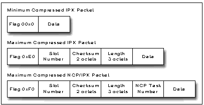
Best and worst case scenarios are based on the use of checksums, which are normally not used in IPX packets. However, if checksums are used they add two bytes to the header. In addition, if the packet length cannot be determined at the Media Access Control (MAC) layer, the compression algorithm adds one byte for packets up to 127 bytes; two bytes for packets from 128 to 16,383 bytes; and three bytes for packets greater than 16,383 bytes (Figure 6).
Figure 6: Compressed IPX and IPX using a flag byte.
PPP Data Compression
Novell introduced software based data compression in its NetWare MultiProtocol Router Plus 2.11. It is based on a predictor algorithm that enables you to compress data over a wide range of interface speeds from 1200 bps to T1/E1.
Although data compression provides some benefit at speeds up to E1, the performance improvement is not as great as on a lower speed 56 Kbps link. This is because as link speed increases, the percentage of throughput improvement decreases because of the additional CPU execution time required in the compression process.
Advantages of Software Compression. Many router vendors offer hardware based compression. However, software based compression offers several key advantages:
It is scalable and easy to upgrade compression functionality without having to purchase new hardware.
New algorithms that support higher speeds can be added to a software based compression implementation while a hardware implementation requires new equipment.
Predictor Data Compression. NetWare MultiProtocol Router Plus uses a predictor algorithm that looks at eight bytes of data at a time and decides if they are in a guess table. A guess table is a hash table that contains previously transmitted data used to predict future data to be transmitted. A flag byte is then inserted with each bit of the flag byte represented if that byte is in the data stream or should be pulled from the guess table. Typically, several of the bytes are in the table and you can obtain at least a 2:1 compression rate.
There is no standard for the implementation of PPP data compression. However, Novell has presented its technology to the Internet Engineering Task Force (IETF). The PPP working group is currently evaluating two draft RFCs written by Dave Rand of Novell. The PPP Reliable Transmission draft documents the use of LAPB with PPP to provide the reliable transport required with compression. The PPP Compression Control Protocol draft documents the negotiation of the use of compression and also the predictor algorithm. Because both the Novell implementation and the draft RFC build on the use of PPP's option negotiation, a router still can communicate with other routers using uncompressed PPP.
Other Compression Standards. In addition to Novell's efforts to standardize PPP data compression, many other companies have been active in the process and a number of alternative algorithms have been submitted to the PPP working group for standardization. For example, Stac Electronics has submitted PPP Stacker LZS Compression, Hewlett Packard has submitted PPP Hewlett Packard PPC Compression Protocol, and Gandalf has submitted PPP Gandalf FZA Compression Protocol. Although these mechanisms are capable of additional compression over the predictor algorithm, they require licensing the protocol from the submitting corporation.
It may appear to you that Novell is showing a bias to PPP throughout this AppNote. However, point to point lines are a widely deployed WAN technology. There is also an effort within the IETF to standardize PPP encapsulation over ISDN and within X.25 and Frame Relay. This will open up PPP compression methods to these other media.
Packet Burst and Data Compression
NetWare 3.11 and earlier releases required that all NCP requests issue acknowledgments prior to the next request in a session. Packet Burst adds a rate based transport to NCP to burst up to 64 KB of data in a single request.
In addition to Packet Burst, Novell has developed another performance enhancement NLMCLarge Internet Packet (LIP) that allows a client to discover the maximum transmission size for a route. This overcomes the limitation of only supporting a 576 byte IPX packet if a router separates a client and server.
Figure 7 shows the difference between moving 8 KB of data across a router with and without Packet Burst and LIP enabled.
Figure 7: Packet burst and LIP operations.
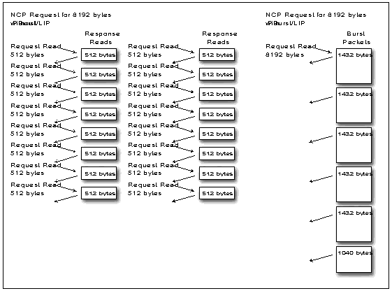
In the first example, after each request for 512 bytes of data, a client must wait for the response prior to the next request. In this case it takes 32 packets to move the data over any media. With Packet Burst and LIP, a single burst read request can be issued for the full 8 KB. Over Ethernet, the operation takes seven packets and there is no turnaround delay between the six packets for acknowledgments. With token ring and a 4,202 byte MTU, the same operation can be performed in three packets. (For more information on how Packet Burst and LIP work, see "Packet Burst Update: BNETX vs. VLM Implementations" in the November 1993 NetWare Application Notes.)
In late 1992, the Packet Burst and LIP functions were merged into the PBURST.NLM for 3.11 servers. This same technology has been integrated into the NetWare 3.12 and 4.01 operating systems. The VLM software in the new Universal Client version 1.1 provides the best operation with Packet Burst and LIP. For WAN operation, there is a new PBURST.NLM for NetWare 3.11 and patches to NetWare 3.12 and 4.01 to improve WAN operation, especially over very low speed links.
Note: The NLM software can be downloaded from NetWire or from ftp.novell.com. The file is NOVLIB/05/PBURST.EXE.
With Packet Burst and LIP, you can obtain dramatic improvements in performance over a WAN. Even local Ethernet maximum packet size is increased for a client and server on a single segment. Over the WAN, adding data compression further increases performance (some benchmark results are included under "PERFORM3 Benchmarks" later in this AppNote). Similar performance gains can also be obtained when combining Packet Burst and LIP with other vendors' data compression solutions.
RIP and SAP Filtering
Routing Information Protocol (RIP) and Service Advertising Protocol (SAP) filters enable you to more effectively manage the LAN and WAN bandwidth used for routing and service overhead. Filters enable you to enable you to connect NetWare services over the WAN and support larger NetWare networks. In addition, filters enhance network security by blocking unauthorized access to network segments or individual servers.
Tip: The NetWare operating system requires a network number in the routing table before it stores a corresponding service on that network in the bindery. You must carefully plan your implementation of RIP filters to ensure that you do not accidentally filter out services that are needed on your network.
NetWare MultiProtocol Router 2.11 and NetWare MultiProtocol Router Plus 2.11 offer inbound RIP and SAP filtering on any interface. NetWare MultiProtocol Router Plus supports outbound RIP and SAP traffic across WAN interfaces. These filters may be applied on a global or per interface basis.
Inbound Filters This type of filter discards packets prior to insertion in the routing and service tables (Figure 8). Inbound filters reduce the impact of RIP and SAP overhead on a router's CPU. For example, by filtering SAP broadcasts, you can not only reduce the amount of SAP overhead in a router service table, but you can also reduce the amount of overhead stored in a server's bindery and written to disk.
Figure 8: Inbound route and service filtering.
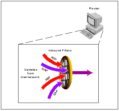
Inbound filters enhance network security because advertisements are blocked on all interfaces. In addition, the router cannot be used as a gateway to a filtered segment, because it does not contain information about that segment in its routing tables.
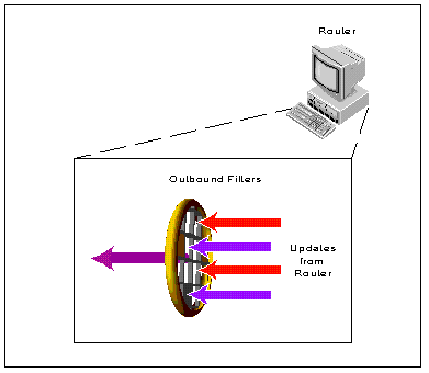
Outbound Filters. These filters are typically used for traffic management and to secure a particular network site (Figure 9). RIP and SAP information is filtered in the updates produced by the router, allowing different views of the network to be advertised from different interfaces. This enables you to give each remote site access only to the resources and networks necessary for communications to that site.
Figure 9: Outbound route and service filtering.
Note: Because third-party routers don't have bindery support, they typically cannot be used as a gateway because clients cannot attach to a device.
NetWare Link Services Protocol
The NetWare Link Services Protocol is a new IPX routing protocol that reduces service and routing overhead on wide area networks. (For an in depth description of NLSP, see the AppNote "NetWare Link Services Protocol: Link-State Routing in a NetWare Environment" in this issue.)
This section explains how NLSP can reduce WAN overhead. It also provides examples of its successful use on the Novell corporate network and NLSP beta sites.
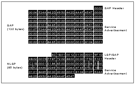
NLSP and SAP. NLSP eliminates SAP overhead on wide area links. Figure 10 shows a service advertisement in a SAP packet and the same service advertisement in an NLSP Link State Packet (LSP). NLSP has more packet overhead on a per packet basis than SAP because it requires management data to maintain the link state database. The overhead is only for the LSPs and not normal IPX traffic forwarded by an NLSP router. However, this larger packet overhead is offset by the ability of NLSP to compute the service name length and use variable length service advertisements, eliminating the need to pad overhead to 48 bytes. In addition, NLSP allows more than seven services per advertisement in a single LSP, which further decreases LSP overhead.
Figure 10: Service advertisement packets.
NLSP Updates. Unlike RIP and SAP which update network routes and services every minute, NLSP only requires updates every two hours -for 1/120 the overhead.
NLSP routers and servers maintain a complete map of the network built from information in the link state database. Unlike RIP's map, which only stores information about the next hop to the destination, NLSP's map includes the complete end to end path for a packet. Because each LSP has an origination and sequence number, it can quickly notify the entire network of a change in network topology and service offerings.
Figure 11 shows what happens when a link fails between two routers in an NLSP network. An NLSP router (Router A) determines a link is down if there are no hello packets or if the router is notified by the Data link layer. Router A then sends a single LSP to the rest of the network (Routers B and C) indicating that a link is down. Routing and service information for networks and services on the other side of a failed link are preserved. NLSP routers mark these networks and services as unreachable. Each router, upon receiving the LSP, converges in fractions of a second.
Once the failure is repaired, NLSP sends an LSP with information on the operable link. Each router in the network still has valid information for networks and services on the far side of the failure if it has not expired.
Figure 11: NLSP operation on link failure.
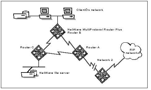
With RIP, the router with the failed link (Router A) advertises to other routers that the attached network and any remote networks learned from the link are unreachable. However, since Routers B and C also learn about the failed routes over multiple interfaces, due to a race condition (with multiple routers that may have multiple paths to a failed link) they get into a "count to infinity" scenario. In this case, when Router B hears that Router A lost connectivity to network 2, Router B reverts to the route advertised by Router C, which is also invalid. But since RIP routers do not contain a map of the network, there is no immediate way to determine the route is invalid.
|
Customer Scenario - NLSP and IP One Novell customer uses NLSP routers, and tunnelsIPX through an IP backbone between the United States and Europe.Prior to using NLSP, routing overhead cost $20,000 on an 850 nodenetwork. With NLSP, routing overhead was reduced to less than1/30 of the RIP and SAP protocols. Idle line costs were reducedto less than $1000 per month. |
With RIP routers, it could take up to seven minutes for the network to converge following a failure. In some network topologies, RIP can take up to one hour to converge. When the link has been repaired, RIP and SAP packets must advertise to every network and service that was unreachable. This could take up to another seven minutes to propagate throughout the network.
Convergence vs. Overhead. As you design your WAN, you will have to make a tradeoff between convergence speed and network overhead. For example, NLSP allows routers to quickly detect network failures and reroute traffic - provided that you reduce hello timers and "router dead" intervals.
Hello packets are packets sent between routers to ensure that neighboring routers are active. The router dead interval determines how many hello packets can be missed before a neighboring router is marked as being down. Increasing the hello packet frequency allows routers to detect failed links and routers more quickly, but it also creates more overhead.
One way to minimize this tradeoff is to use PPP's Link Control Protocol link quality monitoring (LQM) option to assure link integrity. Novell does not offer this feature, but some third-party routers do offer this option. LQM can be tuned to capture degrading performance as well as hard failures. PPP then has mechanisms to inform the network layer protocols of the failure. For multiprotocol internetworks, PPP offers a mechanism with less overhead and that can notify the upper layer protocols of both marginal and failed circuits.
NetWare Directory Services
In its NetWare 4 operating system, Novell included a revolutionary new feature - NetWare Directory Services (NDS). This service replaces the bindery and allows you to create a global Directory for your entire network that is easier to manage and update. This section discusses how NDS can improve WAN efficiency. (For more information on NetWare 4 and NDS, see the April 1993 special edition of NetWare Application Notes and subsequent AppNotes on NetWare 4.)
|
NLSP in Novell's Network Novell uses RIP/SAP filtering to keep SAP overheadto a manageable level. Even with filtering, Novell has portionsof its network with over 1,600 reachable services and 2,400 routes.RIP and SAP protocols completely saturate a 9.6 Kbps line, leavingno bandwidth for payload. NLSP takes about five minutes to transferthis topology between two routers, and bandwidth is still availablefor users because of the pacing of the update over the WAN link.Should a link failure occur, convergence is immediate becauseonly the changed information needs to be propagated, not the entiretopology. Following convergence, link overhead due to NLSP isunder five percent. |
NDS and SAP. NLSP eliminates the SAP broadcasts by transporting service information in the LSPs. NDS places the service information in a Directory, which reduces SAP broadcasts on the network. NDS represents items such as users, volumes, print servers and file servers as objects in an X.500-like Directory. With NDS, as soon as bindery emulation is turned off, most SAP traffic is eliminated because services are now leaf objects in NDS containers. Outside of a specific context, services no longer need to be known.
Note: NDS still uses SAP to advertise the existence of Directory servers, and NLSP will improve the transport of these SAPs.
There is more information on designing a Directory tree and the corresponding partitioning and replica strategy than can be covered in this AppNote. The main point to remember here is that a Directory tree needs to be designed with impact on network bandwidth and performance requirements in mind.
Time Synchronization. By default, the time synchronization component of Directory Services uses SAP to advertise the presence of time servers. Custom configuration turns off this SAP process and replaces it with a time configuration file on each server. Along with turning off the time-related SAP, this also avoids disruption of time synchronization due to accidental misconfiguration of new servers. (For further information on tuning time synchronization, see "Time Synchronization in NetWare 4.x" in the November 1993 NetWare Application Notes.)
Static Routing
Static routing eliminates RIP and SAP broadcasts on designated links because routing and service traffic are not transmitted on a circuit. Instead, statically configured route and service databases are maintained by each router.
You can augment static routing with on demand routing to increase optimization of your WAN link. With on demand routing, a circuit is not activated until an application forwards data. The router must also perform additional work to spoof packets that may unintentionally activate the line. For example, a watchdog packet - one that is exchanged between a client and server to verify a connection - can activate an on demand circuit. However, router vendors will allow you to choose whether or not a router will spoof watchdog packets.
Static and on demand routing creates some administrative overhead to update static routing and service tables. With the implementation of NLSP, router vendors will be able to provide tools that automate the configuration of static routes and services. You will still have to initiate the process for each pair or routers configured for static routing.
PERFORM3 Benchmarks
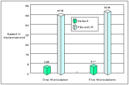
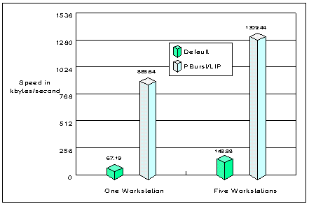
Novell has done extensive testing of WAN performance using NetWare MultiProtocol Router Plus. Figures 12 through 17 show the test results using PERFORM3 and the parameters 12 128 4096 1024, with 486/33 clients and servers. The server sends 4,096 byte packets for 12 seconds; 3,072 byte packets for 12 seconds; 2,048 byte packets for 12 seconds; and finally 1,024 byte packets for 12 seconds.
Note that these are benchmark results - performance gains with NCP and SPX may not be the same. NCP and SPX are both sensitive to latency, and it may be that the additional processing time of compression does not offset the gains in bandwidth reduction.
As an example, Figure 12 shows a standard PPP 56 Kbps line (baseline) versus PPP data compression on the same 56 Kbps line. You can see performance improvements on the order of 3 to 1 with PPP data compression.
Figure 12: 56 Kbps circuit - compressed vs. baseline.
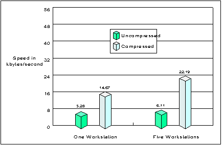
Figure 13 shows the same test, but compares the baseline with Packet Burst and LIP enabled. From the baseline test, you can see a 9:1 improvement, with the clients utilizing nearly the entire line.
Figure 13: 56 Kbps circuit - Packet Burst vs. baseline.
You are probably thinking that compression is nice, but you can get much better improvement with Packet Burst and LIP. Figure 14 shows you the benefits gained by combining the two technologies together. It is now possible to drive the 56 Kbps circuit at two or three times its rated capacity.
Figure 14: 56 Kbps circuit - Packet Burst and compression vs. baseline.
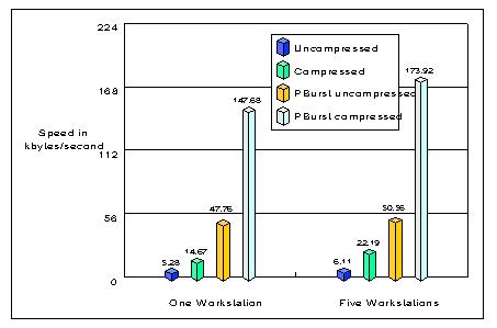
Figure 15 shows the effects of using data compression on a T1 circuit. In this example, the server has trouble delivering sufficient data to the compression engine to obtain meaningful compression. PERFORM3 results are very modest, in the 5 to 20 percent improvement range.
Figure 15: T1 circuit - compressed vs. baseline.
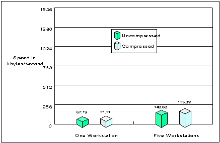
Figure 16 shows you how to maximize T1 lines by turning off compression and turning on Packet Burst and LIP. These results are comparable to the results from the 56 Kbps test. While a single workstation has difficulty filling a T1 line, five workstations are within 20 percent of line capacity.
Figure 16: T1 circuit - Packet Burst vs. baseline.
Given the modest results of compression without Packet Burst, you might expect compression to add little to Packet Burst. However, compression has a geometric effect when coupled with Packet Burst and LIP (Figure 17).
Figure 17: T1 circuit - Packet Burst and compression vs. baseline.
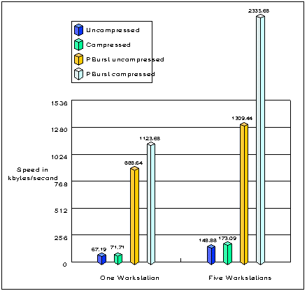
Recall that compression gave less than a 20 percent gain with 5 workstations, yet when given a Packet Burst stream, compression increases the result by over 75 percent. The results with a single stream are from less than 7 percent gain to over 25 percent gain in line efficiency.
Conclusion
This AppNote has covered how line overhead can be reduced by tuning existing routing protocols or implementing new routing protocols, as well as through the use of header and data compression. Increases in payload capacity can be obtained through Packet Burst and LIP technology and further enhanced by data compression.
Glossary of WAN-related Terms
compressed IPX. An extension of the Van Jacobson compression for the IPX protocol.; This specification was developed by Telebit Corporation and shows how to reduce IPX headers from 30 bytes to a range of one to seven bytes. It also provides the option of compressing the transport header of NCP.
compression dictionary. A hash table that contains previously transmitted data that is used to predict future data to be transmitted. Also known as a guess table.
data-link header compression. A method of compressing header information at the data-link layer of the Open Systems Interconnection (OSI) model.
guess table. See compression dictionary.
HDLC. High-level data-link control. Bit-oriented, synchronous protocol that applies to the data-link layer of the OSI model.
LAPB. Link Access Procedures-Balanced. Consultative Committee for International Telegraphy and Telephony (CCITT) bit-oriented protocol similar to the synchronous data-link control (SDLC) protocol.
line overhead. The part of a WAN circuit that contains the media's framing routing protocol, and network-layer protocol overhead.
LIP. Large Internet Packet. A performance enhancement NLM that allows a client to discover the maximum transmission size for a route. This NLM has been combined with Packet Burst in the PBURST.NLM.
LSP. Link-state packet. A packet generated by a router in a link-state routing protocol which lists that router's neighbors and attached networks.
NDS. NetWare Directory Services. An object-oriented directory database that replaces the bindery of the NetWare 3 platform. NDS enables you to create a global X.500-like directory for your network.
NLSP. NetWare Link Services Protocol. IPX link-state protocol used by IPX routers to share information about their routes with other devices on the network. Enables network managers to interconnect small or large networks without routing inefficiencies.
network-layer header compression. A method of compressing header information at the network layer of the OSI model. It can be used with a wide range of WAN media, including X.25, PPP, and Frame Relay.
Packet Burst. A performance enhancement NLM that adds a rate-based transport o NCP to burst up to 64 KB of data in a single request.
payload capacity. The speed at which data moves through a WAN circuit.
Van Jacobson Compression. A method for compressing TCP/IP header information, reducing he header from 40 bytes to between three and five bytes.
* Originally published in Novell AppNotes
Disclaimer
The origin of this information may be internal or external to Novell. While Novell makes all reasonable efforts to verify this information, Novell does not make explicit or implied claims to its validity.