Communication Basics and Open Data-Link Interface Technology
Articles and Tips: article
Associate Consultant
Systems Engineering Division
01 Nov 1992
This Application Note provides a basic foundation for understanding network communications and introduces Novell's Open Data-Link Interface (ODI) technology. ODI offers numerous advantages over traditional LAN drivers, including support for multiple protocol stacks and frame types on a single workstation, more flexible memory management, easier configuration options, and increased performance over other multiple-protocol options. This is the first in a series of AppNotes on ODI-related topics.
- Introduction
- Data Communication Basics
- Open Data-Link Interface (ODI)
- ODI: An Example
- Summary
- Appendix: Frame Types
Introduction
This AppNote provides a basic conceptual foundation for network communications and introduces Novell's Open Data-Link Interface (ODI) technology. This is the first AppNote in a series on ODI-related topics. Future AppNotes in this series will cover more specific areas such as:
ODI vs. dedicated IPX drivers
Media Access Control (MAC) frame types
Installing ODI and configuring the NET.CFG file
A working knowledge of data communication processes is essential to understanding Open Data-Link Interface technology. To establish a common foundation for discussion, this AppNote begins with an summary of basic network communications and graduates to an overview of ODI architecture.
Data Communication Basics
The four basic elements for data communication on a network are listed below and illustrated in Figure 1:
Sender-the device that creates and transmits the data.
Message-the data to be sent. It could be a spreadsheet, database, or document, converted to digital form.
Medium-the physical material that connects the devices and carries the data from the sender to the receiver. The medium may consist of an electrical wire or airwaves.
Receiver-the destination device for the data.
Figure 1: For data communication to take place on a network, there must be a sender, a receiver, a message, and a medium.

To communicate with other devices, a sending device must know and follow the rules for sending data to receiving devices on the network. These rules for communication between devices are called protocols.
Numerous standards have been developed to provide common foundations for data transmission. The International Standards Organization (ISO) has divided the required communication functions into seven levels to form the Open Systems Interconnections (OSI) model. Each layer in the OSI model specifies a group of functions and associated protocols used at that level in the source device to communicate with the corresponding level in the destination device (see Figure 2).
Figure 2: The OSI model divides data communication functions into seven distinct levels or layers.

Devices desiring to communicate on a network must abide by the protocol rules at each layer. As shown in Figure 3, a message from the sender travels down through each layer in segments (or packets). Each layer adds protocol information to the packet of data. At the receiving end, the corresponding layers use the added information to route the packet and initiate commands. After the information is removed at each corresponding layer, the remaining packet of data is presented to the next higher layer.
Figure 3: When a message is sent, the various protocols add and remove their own information at each layer.

Network Communication Components
To communicate on a local area network, a device must contain the following hardware and software components (see Figure 4):
LAN board
Software driver
Communication protocol stack
Figure 4: The three main components for network communication are the LAN board, a driver, and a protocol stack.
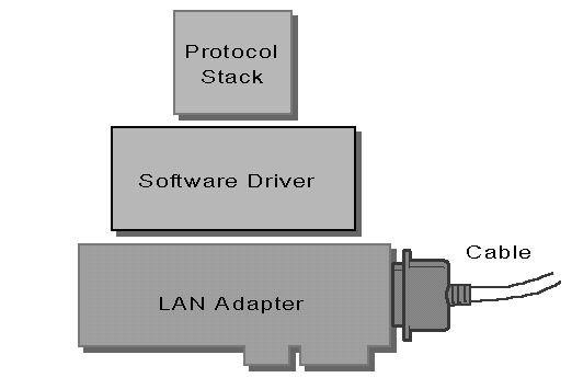
LAN Board. Each device on a network requires a LAN board, also referred to as a network interface card (NIC) or network adapter. The LAN board forms the electronic hardware link to the transmission medium. A LAN board knows and follows the rules for placing data onto a specific type of network medium. These rules are called media access methods.
Each type of media has unique rules for accessing the network (wire) and sending information. Common access methods include Carrier Sense Multiple Access with Collision Detection (CSMA/CD), Token Passing, and Token Bus. By following the media access rules, the LAN board converts data into a stream of binary impulses and transmits the impulses onto the wire. The LAN board also receives incoming impulses and converts the stream of impulses back into binary data.
Software Driver. To interface with the transmission hardware, LAN boards need instructions from a software program called a driver. (In this AppNote, the term "driver" refers to the LAN board software driver.) The driver appends and removes addressing, upper-layer protocol, and error-checking information to form a "frame."
The packet must adhere to a common frame format or frame type to access the medium and communicate with other devices on the network. The frame type designates the placement of values in a specified format needed to access the medium (wire) and route the data to its destination.
Token-Ring networks can use the following frame types:
Token-Ring 802.2
Token-Ring SNAP
Ethernet networks can use the following frame types:
IEEE Standard 802.2
Ethernet SNAP
Ethernet II
Ethernet 802.3 (Raw)
The first three Ethernet frame types have fields to specify a specific upper-layer protocol stack to be used; the Ethernet 802.3 frame type does not include a field to specify an alternate upper-layer protocol stack. The only communication protocol that uses Ethernet 802.3 is Novell's IPX/SPX protocol stack. (For a complete listing of frame types and formats, see the Appendix.)
Communication Protocol Stacks. A communication protocol stack defines the rules associated with presenting, transmitting, and receiving data by a device on a network. Protocols exist at all levels of data communication. However, for the purposes of this article, a communication protocol (or protocol stack) means all protocols above the Data Link layer of the OSI model.
The protocol stack converts information from applications (or higher-layer protocols) to data the LAN board/driver can interpret. The communication protocol stack also provides additional routing and connection services by adding its own set of information to all packets sent through the protocol stack.
Many different communications protocol stacks have been developed by computer manufacturers, government agencies, and telecommunications companies. Each protocol stack defines its own unique rules and methods for data transmission. Two of the most common communication protocol stacks are:
Internet Packet Exchange / Sequenced Packet Exchange (IPX/SPX). IPX and SPX are based on Xerox's Internetwork Datagram Protocol. IPX/SPX allows applications running on NetWare workstations to use NetWare features to communicate directly with other workstations, servers, or devices on the internetwork.
Transmission Control Protocol / Internet Protocol (TCP/IP). Developed by the Department of Defense and popularized by Unix systems, TCP/IP allows access to information at schools, government agencies, and businesses all over the world.
Some applications are protocol dependent, meaning they are written to use a specific protocol stack and cannot access or use any other protocol stack.
Traditional Protocol Interface Solutions
Traditionally, protocol stacks have been linked directly to the LAN board/driver. For example, in NetWare v2.x and earlier, a workstation containing an NE1000 LAN board had to have the NE1000 driver linked directly to the IPX communication protocol stack, resulting in a customized IPX.COM file. IPX.COM operates as a terminate-and-stay-resident (TSR) program that monitors communication between the computer's operating system and the network devices.
Figure 5: With dedicated IPX drivers, the protocol stack is linked to the driver to form a customized IPX.COM file.
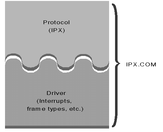
The IPX.COM file generated by Novell's WSGEN utility contains all the configuration information for the LAN board, driver, and protocol stack: interrupts, memory addresses, MAC frame types, and protocol header information. Because the driver cannot be separated from the protocol stack, the user is limited to one protocol stack per LAN board.
If a network device needed to communicate over more than one protocol stack, there were limited solutions available:
Purchase a multiple-protocol LAN board that links directly to two or more communication protocol stacks. These boards are expensive and often unreliable.
Use software packet drivers, which pass each packet (or frame) to each protocol stack in turn until the packet is claimed. This "chaining" of protocol stacks reduces the performance of network devices.
Install media-aware interfaces such as Network Device Interface Specification (NDIS). NDIS drivers work the same as software packet drivers. However, NDIS is media-aware, which means that the protocol stack knows and cares what the lower-transmission layers use as the media type (frame types and access method). NDIS forces the protocol stack to insert media-access information into the MAC header.
Open Data-Link Interface (ODI)
Using a LAN board that is directly linked to a communication protocol stack limits the LAN board/driver to one protocol stack with one frame type. To overcome these limitations, Novell developed the Open Data-Link Interface driver specification. With ODI, a single workstation can transparently communicate with several different protocol stacks, using just one LAN driver and LAN board.
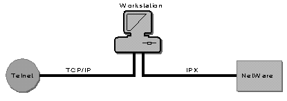
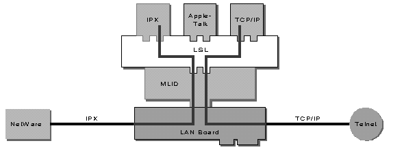
Using ODI, a workstation can access several protocol-specific applications and services concurrently. For example, from a single workstation a user can access TCP/IP-specific services like Telnet while being logged into a NetWare server over IPX, as shown in Figure 6.
Figure 6: ODI lets a user access protocol-specific services, such as NetWare and Telnet, simultaneously.
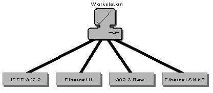
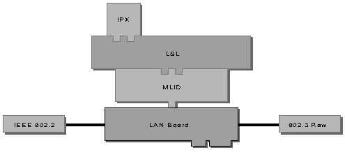
ODI also allows communication between devices with different frame formats. For example, a single workstation can communicate with any devices using one of the four Ethernet frame types (see Figure 7).
Figure 7: ODI allows a single workstation to communicate with devices using different frame formats.
This flexibility is useful when the user needs to access resources in multivendor, multiprotocol networks.
ODI Architecture
Architecturally, ODI technology consists of the following components, illustrated in Figure 8:
Multiple Link Interface Driver (MLID)
Link Support Layer (LSL)
Communication protocol stacks
Figure 8: The Open Data-Link Interface architecture.
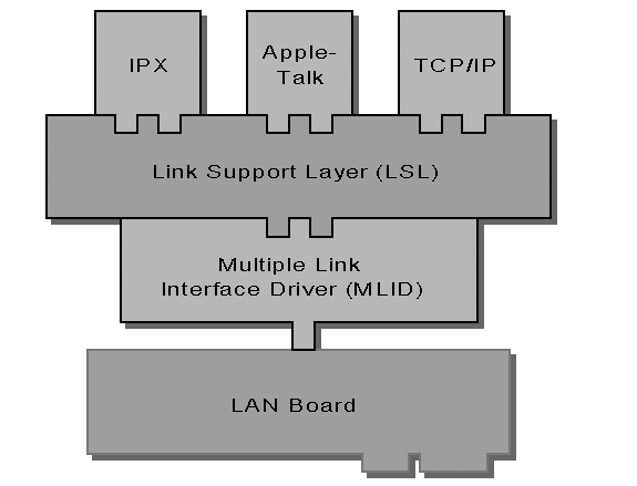
Multiple Link Interface Driver (MLID). Multiple Link Interface Driver is the ODI name for a LAN board driver developed according to ODI specifications. In fact, the terms MLID and LAN driver can be interchanged. The MLID performs all the LAN driver functions mentioned earlier, and it is designed to interface with the ODI Link Support Layer.
Unlike the traditional dedicated IPX driver, an MLID is not directly linked to a communication protocol stack. When a packet is received, the MLID is responsible for removing the media access information (MAC header) and passing the packet to the Link Support Layer.
Link Support Layer (LSL). The Link Support Layer is the key to ODI's openness and flexibility. The LSL functions as a switchboard operator, directing communication traffic between the MLID and the protocol stacks.
Because ODI allows the network to support many different protocols stacks, the LAN board driver in a single workstation will receive packets destined for different protocol stacks. When it receives a packet from the MLID, the LSL interprets information stored in the packet's protocol identification field(s) and uses it to pass the packet to the assigned protocol stack (see Figure 9).
Figure 9: The LSL acts as a switchboard operator, directing traffic between the MLID and the protocol stacks.
Protocol Stack. The LSL incorporates a Multiple Protocol Interface (MPI) which allows it to interface with multiple communication protocol stacks. The protocol stack receiving the packet is unaware of the media or LAN board type. It simply receives the packet formatted according to the rules associated with that protocol stack. The protocol stack removes its specific header information and prepares the packet to be passed on to the higher-layer protocol or application.
Benefits of Using ODI
In addition to allowing multiple protocols and frame types, ODI offers several other benefits for network users.
Improved Memory Management. Due to ODI's modular design, it provides more flexibility for memory management. Smaller modules require smaller portions of contiguous memory, which makes it easier to load them into high memory. Each module can also be loaded and unloaded from the command line without rebooting the computer.
Easier Configuration. Configuration changes for the LAN board, LSL, and protocol stack can be made by simply editing the a text file called NET.CFG. No workstation generation programs (such as WSGEN) are necessary. NET.CFG encompasses all configuration features previously available in SHELL.CFG, like PREFERRED SERVER and SHOW DOTS.
Increased Performance over Other Multiprotocol Options. Rather than passing all frames to each protocol stack as NDIS and packet drivers do, the LSL directs the packet to its specific stack. This direct routing increases network performance.
Protection Against Obsolescence. As new protocol stacks are developed, they will be able to communicate with existing MLIDs. Similarly, new MLIDs can be used without changing protocol stacks (see Figure 10). Novell and the networking industry will not support new LAN board drivers linked directly to protocol stacks.
Figure 10: With ODI, new protocol stacks and MLIDs can be added as they become available.

More Flexible Configuration Options. Using Open Data-Link Interface technology offers networks more flexibility for configuring workstations. Here are some examples of the many configuration options available using ODI.
Example 1: One LAN board and One Protocol Stack with Multiple Frame Types
ODI technology provides the same functionality as dedicated drivers, allowing a workstation with one LAN board to communicate with a single protocol stack. However, ODI allows that workstation to communicate with other devices using multiple frame types, as shown in Figure 11.
Figure 11: With ODI, a single workstation with one LAN board and one protocol can use multiple frame types.
(For a list of common LAN boards and supported frame types, see the Appendix.)
Example 2: One LAN Board and Multiple Protocol Stacks
With ODI, a workstation with one LAN board can communicate using two or more protocol stacks. For example, the workstation pictured in Figure 12 contains one Ethernet LAN board. Through the LSL, the LAN driver is linked to both the IPX protocol stack and the IP protocol stack.
Figure 12: An ODI workstation with one LAN board can communicate using several protocols.
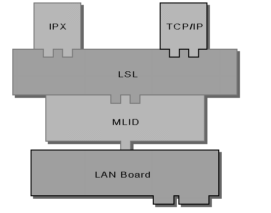
Each received packet is stripped of its media-specific information and passed to the LSL. The LSL interprets the protocol identification information and routes the packet to its assigned protocol stack. Even though there may be only one physical LAN board in the computer, the effect is the same as having multiple LAN boards and multiple LAN drivers.
Example 3: Multiple LAN Boards and One Protocol Stack
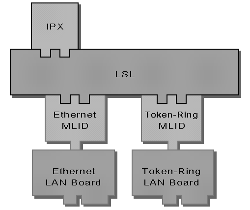
Using ODI technology, a workstation with two or more LAN boards connected to different media networks can communicate with one protocol. For example, the workstation pictured in Figure 13 contains a Token-Ring LAN board and an Ethernet LAN board. Packets received from both network segments are passed up to the IPX protocol stack.
The Token-Ring board removes the media-specific frame and passes the packet to the LSL which directs it to the assigned IPX protocol stack. The Ethernet LAN board removes its media-specific information, passes it to the LSL which directs it to the assigned IPX protocol stack.
Figure 13: An ODI workstation with multiple LAN boards connected to different networks can use one protocol.
Example 4: Multiple LAN Boards and Multiple Protocol Stacks
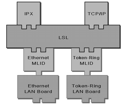
A single workstation connected to two networks of different media types can use ODI to use multiple protocols. For example, the workstation pictured in Figure 14 contains an Ethernet LAN board and a Token-Ring LAN board. The Ethernet board communicates through the LSL to the IPX protocol stack, while the Token-Ring LAN board communicates to IP.
Figure 14: A workstation with multiple LAN boards can use ODI to communicate with multiple protocols.
Example 5: Multiple Desktop Operating Systems on One NetWare Network
Novell's use of ODI components on the NetWare server allows communication between dissimilar workstation operating system on a single network. For example, the NetWare server pictured in Figure 15 allows DOS, UNIX, and Macintosh workstations to share resources on a single network.
Figure 15: ODI on the NetWare server allows different workstation operating systems to coexist on the network.

Packet Flow Using Open Data-Link Interface
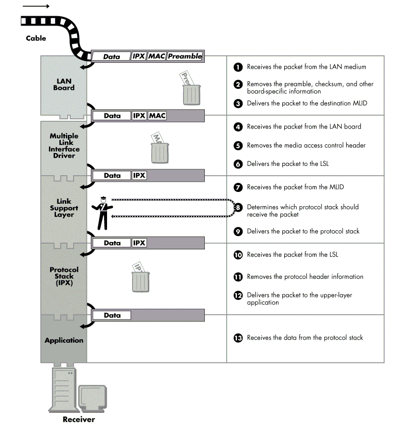
To better understand how ODI works, it is helpful to trace the path of a data packet as it travels from source to destination. When the source application needs to transmit data to another network device, the application sends the data through the upper-layer protocols to the application's communication protocol stack. The transmitted data flows through the protocol stack to the LSL and on to the LAN driver. To successfully communicate the data, the same protocols and applications must exist at all levels of the OSI model.
The events illustrated in Figures 16 and 17 outline the transfer of data from the source application to the destination application.
Figure 16: ODI packet flow from source application to medium.
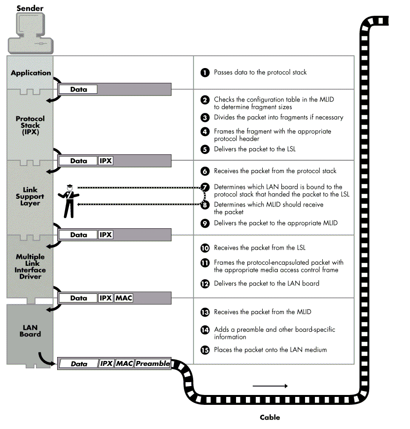
Figure 17: ODI packet flow from medium to destination application.
ODI: An Example
To reiterate the concepts introduced in this AppNote, let's look at a more specific example of how a particular application uses ODI to send data from a sender to a receiver. This example involves the NetWare SEND utility, an IPX application that allows peer-to-peer communication of brief messages between network workstations. Suppose you want to go to lunch with Martha. At your workstation, you (the sender) type:
SEND "Let's do lunch" to MARTHA <Enter<
The following steps then take place (for simplicity, we'll ignore extraneous Netware Core Protocol (NCP) packets):
The SEND utility checks the bindery for user MARTHA's ID number and uses that to obtain Martha's destination address. The destination address consists of a network address and node number. For this example, the network address is FEEDFACEh; the node address is 00001A311356h.
Because the SEND utility is an IPX application, the message "Let's do lunch" is passed down through the OSI Presentation and Session layers to the IPX protocol stack.
IPX checks the LAN driver's configuration table for the minimum and maximum packet size and divides the data string into the appropriate sizes. In this case, the entire message will fit in one packet.
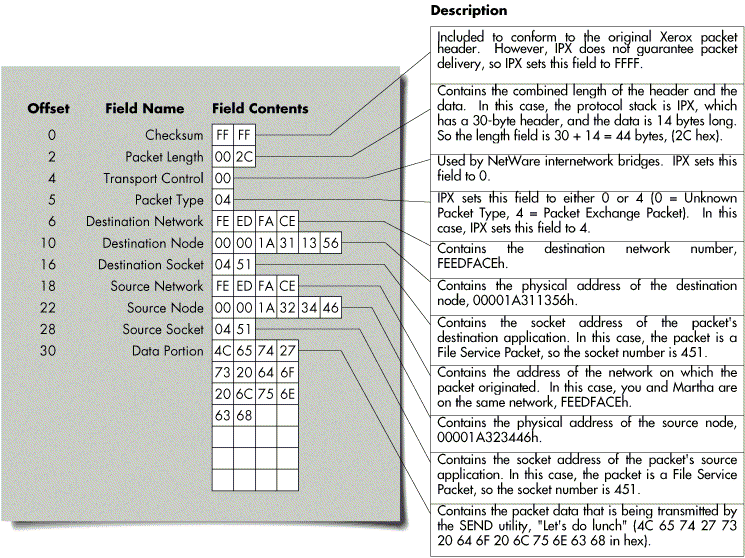
IPX encapsulates the packet with an IPX header and inserts the destination and source addresses into the packet(see Figure 18). In this example, the source network address is FEEDFACEh and the node address is 00001A323446h.
Figure 18: IPX adds its own protocol header to the data and fills in the fields as illustrated.
IPX hands the packet to the LSL.
The LSL checks the board number to which the protocol stack is bound and passes the packet to the appropriate LAN driver.
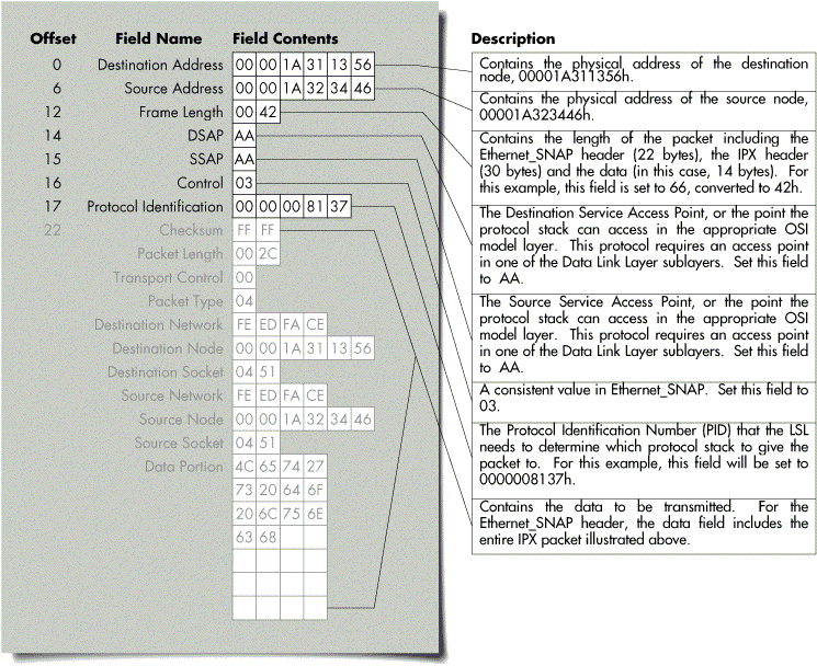
The LAN driver encapsulates the packet in the appropriate frame type - in this instance, Ethernet SNAP. Figure 19 illustrates the Ethernet SNAP frame and the contents of each field.
Figure 19: A graphic representation of the packet formatted aan Ethernet_SNAP frame. graphic representation of the packet formatted
The LAN driver passes the packet to the LAN board, which adds an 8-byte preamble to the packet. It also calculates a CRC and adds that value and other board-specific information to the packet. The LAN board then puts the packet on the wire.
The destination LAN board (in Martha's workstation) receives the packet.
The LAN board uses the preamble to adjust itself to the proper timing so it can receive the bits correctly.
The LAN board removes the preamble and checksum from the packet and passes the packet to the LAN driver.
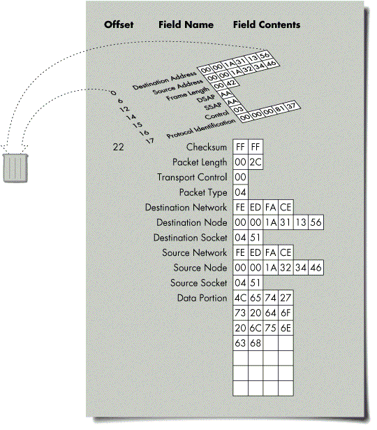
The LAN driver strips off the frame header, which in this example is the Ethernet SNAP header (see Figure 20).
Figure 20: Once the receiving MLID strips off the frame header, the packet is ready to be passed up to the LSL. receiving MLID strips off the frame header,
The LAN board gives the Protocol Identification number (PID) to the LSL. This enables the LSL to determine which LAN board the protocol stack is bound to.
The LSL checks the PID and passes the packet to the appropriate protocol stack (IPX in this case).
IPX strips off the IPX header. The packet now looks like this (the hex representation of the string "Let's do lunch"):
4C 65 74 27 73 20 64 6F 20 6C 75 6E 63 68
IPX passes the message string up through the OSI Presentation and Session layers to the NetWare shell.
The receive portion of the SEND utility displays the message on Martha's monitor as shown below:
From SBEARNSON[2]: Let's do lunch (CTRL-ENTER to clear)
Note: The SEND utility is able to display your username in the "From" field on the monitor by using information found through the connection between the machines that the utility established earlier.
The message travelled from the sender to the receiver using the rules defined at each level of communication. At each level, routing and connection information was added, or the data was converted to another format. The receiving device followed the same rules to remove the added information and transparently present the data to the user.
Summary
This AppNote has introduced Novell's Open Data-Link Interface, a platform for current and future technologies that allows multiple protocols and frame formats to exist on a single workstation. ODI also offers flexible memory management, easier configuration options, and increased performance over other multiple-protocol options.
Future AppNotes in this series will contrast ODI and dedicated IPX drivers in more detail, and more thoroughly discuss ODI installation and configuration of the NET.CFG file.
Appendix: Frame Types
Ethernet 802.2
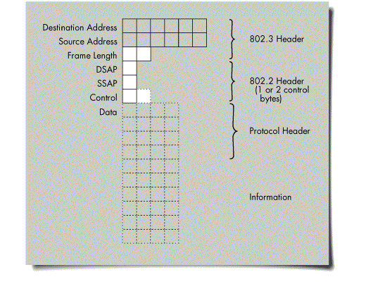
In Ethernet 802.2 packets, the FrameLength field (bytes 13 and 14) contains a value less than or equal to 1500 decimal. If the next three fields (DSAP, SSAP, and Control) are not AAh, AAh, and 03h respectively, the packet is an Ethernet 802.2 frame.
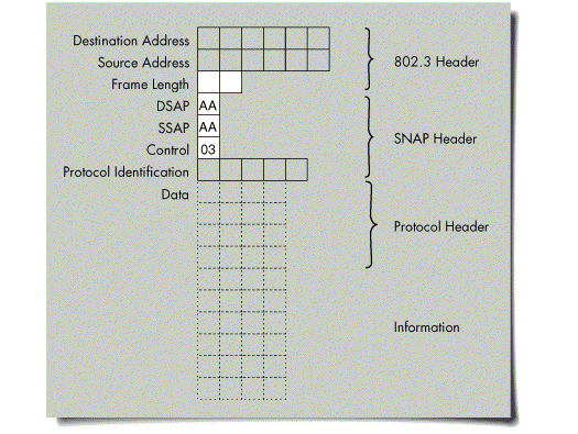
Ethernet SNAP
In Ethernet SNAP packets, the FrameLength field (bytes 13 and 14) contains a value less than or equal to 1500 decimal. The next three fields (DSAP, SSAP, and Control) contain the values AAh, AAh, and 03h respectively.
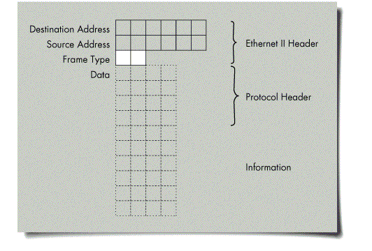
Ethernet II
In Ethernet II packets, the FrameType field (bytes 13 and 14) contains a value greater than 1500 decimal.
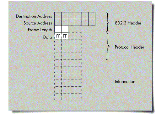
Ethernet 802.3 (Raw)
In Ethernet 802.3 raw packets, the FrameLength field (bytes 13 and 14) contains a value less than or equal to 1500 decimal. In addition, the first two bytes of the Data area (bytes 15 and 16) contain the values FFh and FFh.
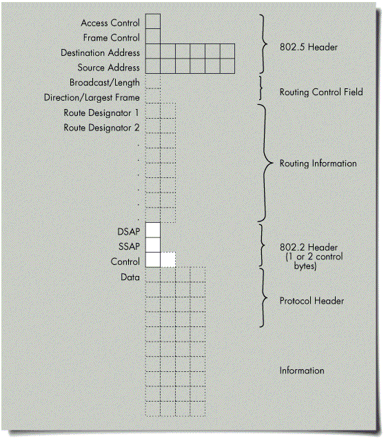
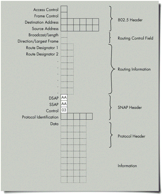
Token Ring 802.2
In Token-Ring 802.2 packets, the DSAP, SSAP, and Control fields are not AAh, AAh, and 03h respectively.
Token Ring SNAP
In Token-Ring SNAP packets, the DSAP, SSAP, and Control fields are AAh, AAh, and 03h respectively.
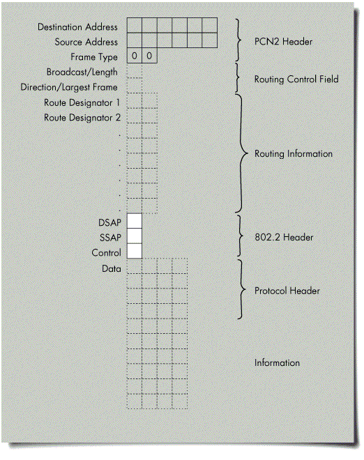
PC Network II 802.2
In PCN2 802.2 packets, the DSAP, SSAP, and Control fields (bytes 15, 16, and 17) are not AAh, AAh, and 03h respectively.
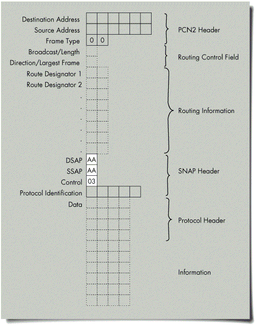
PC Network II SNAP
In PCN2 SNAP packets, the DSAP, SSAP, and Control fields (bytes 15, 16, and 17) are AAh, AAh, and 03h respectively.
RX-Net Short
In RX-Net short packets, the ByteOffset field (byte 3) contains a non-zero value.
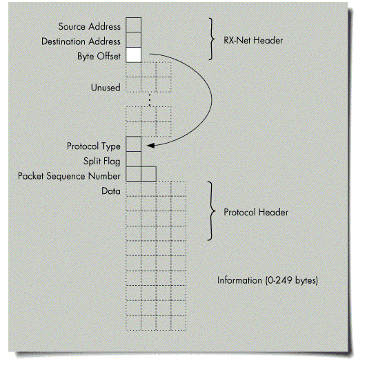
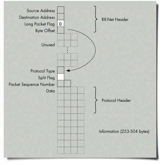
RX-Net Long
In RX-Net long packets, the third byte of the packet (LongPacketFlag) is 0, and the second byte after the unused portion of the packet (SplitFlag) is not FFh.
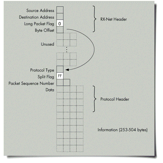
RX-Net Exception
In RX-Net exception packets, the third byte (LongPacketFlag) is 0, and the second byte after the unused portion of the packet (Pad2-SplitFlag) is FFh.
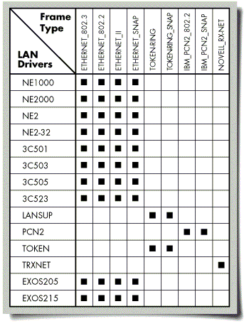
LAN Drivers and Frame Types
The following chart lists the frame types supported for each LAN driver supplied by Novell.
* Originally published in Novell AppNotes
Disclaimer
The origin of this information may be internal or external to Novell. While Novell makes all reasonable efforts to verify this information, Novell does not make explicit or implied claims to its validity.