Understanding Token-Ring Source Routing
Articles and Tips: article
Senior Technical Writer
Systems Engineering Division
PAUL TURNER
Senior Consultant
Systems Engineering Division
01 May 1991
This AppNote describes how source routing works with the IEEE 802.5 Token-Ring Network. As the first in a series of AppNotes on NetWare's source routing implementation, this document explains basic concepts necessary to understand how source routing works in a generic Token-Ring environment. It covers frame structure, route determination processes, and source-routing bridge operation.
Special thanks is given to Stephen Belisle and Bob Ross of Novell for their invaluable input in the creation of this AppNote.
- Introduction
- What is Source Routing?
- Why Source Routing?
- How Source Routing Works
- A Closer Look at Route Determination
- Broadcast Traffic Overhead
- Parallel Bridges and Load Balancing
- Conclusion
- Appendix A: Use of Terms
- Appendix B: Token-Ring Frame Structure
- Appendix C: Bibliography
Introduction
The purpose of this AppNote is to provide a solid understanding of Token-Ring source routing. This document supplies critical conceptual information rather than extensive performance benchmarking data. This information will be most valuable to people who are designing, implementing, and administering complex Token-Ring networks. Future AppNotes on this subject will include specific implementation notes for source routing in a mixed-vendor environment.
The information for this AppNote came from various publication (listed in the bibliography) and from interviews with engineers and consultants familiar with source routing n the Token-Ring environment.
In this AppNote, we use a combination of IBM, Novell, and industry terminology (unless otherwise noted):
"Frame," synonymous with "packet," is used to denote the basic unit of transmission on the network.
"Bridge" refers to a device using the ISO Data Link layer for frame-forwarding instructions(such as an IBM Token-Ring Network bridge). There are two distinct types of bridges -transparent bridges and source routing bridges. The term bridge as used in this AppNote refers to a source-routing bridge.
"Router" refers to a dedicated device using the ISO Network layer for frame-forwarding instructions (such as a NetWare "bridge," which is now called a router). A ring station that passeson source routing packets (at the Data Link layer) is not considered a router in the same sense as a specialized router is.
"Broadcast" refers to two things:
1) An all-stations broadcast (common to all Token-Ring networks)
2) A route determination broadcast (specific to source routing) We will define these two terms explicitly later. Since these are two distinct broadcast types, we'll use these labels to avoid confusion.
Appendix A lists and clarifies additional terms that IEEE, IBM, and Novell have come to use in different ways.
What is Source Routing?
IEEE has defined a method of routing which allows one node to communicate with another node up to thirteen rings away (fourteen rings total). This method of routing, called "source routing," is necessary when at least two rings are interconnected by bridges.
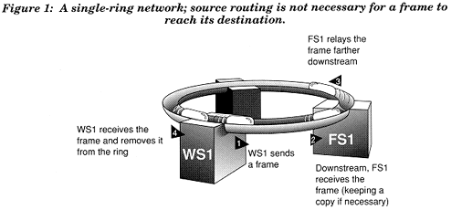
Single-ring networks do not require source routing. The Token-Ring architecture requires a frame on a single ring to automatically make a loop around the ring, so all stations can see the frame. Each station forwards the frame it receives from the station upstream, keeping a copy if necessary. When the transmission arrives back where it started, the originating station removes the frame from the ring. (See Figure 1).
Figure 1: A single-ring network; source routing is not necessary for a frame to reach its destination.
Multiple-ring networks, in which rings are linked by source-routing bridges, need an additional routing procedure to define how a frame originating on one ring crosses a bridge to another ring. This is where source routing comes in.
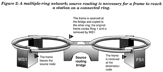
A source-routing bridge will only pass certain types of frames from one ring to another ring (these frame types are presented in detail later). Source-routing bridges get their instructions for passing a frame between rings by reading source routing information placed at the beginning of the frame. The source station (which originates the frame) is responsible for inserting these routing instructions in the frame before it is sent. Hence, the term "source routing." Source routing defines the ring-bridge-ring routing information that is contained in the frame for bridges to read.
Source routing is illustrated in its simplest form in Figure 2, where WS1 sends a frame through a bridge to FS1.
Figure 2: A multiple-ring network; source routing is necessary for a frame to reach a station on a connected ring.
Stated another way, source routing occurs when the source station determines the route that its data travels on the way to a destination station on another ring. After determining an appropriate route, the source station then includes routing information in subsequent frames sent to the destination station.
Because a station must know the route to another station before it can communicate with that station, source routing also defines how a station can determine if a route is available. Route determination is especially important where multiple routes exist between two stations, as shown in Figure 3.
Figure 3: Two routes between the source and the destination on a multiple-ring network; normally, the originating station chooses which path to use.
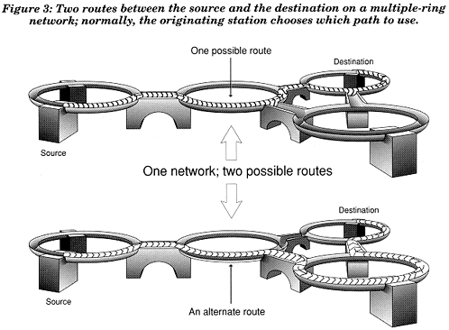
In the IBM and Novell implementations, the source station chooses which route its data will follow to reach the destination station. The destination station begins using this rout after it receives the first explicitly routed frame from the source station.
By design, source routing uses distributed routing tables rather than centralized routing tables. In source routing, bridges do not keep routing tables; instead, the tables are distributed over the network at each ring station. An individual station checks its own routing information table to find the route that frames must travel to reach the stations it communicates with.
This distributed method of routing contrasts with routing methods that use centralized routing tables (such a NetWare or TCP/IP) in two ways: (1) the location of the routing tables; and (2) the OSI layer used (source routing uses the Data Link layer and NetWare routing uses the Network layer). In centralized routing, a specialized router acts as an intelligent frame-forwarding device, maintaining a table of segments and the available routes to reach them. (For more information on NetWare routing, please refer to "NetWare Communications Processes" in the September 1990 issue of NetWare Application Notes.)
Why Source Routing?
Without a way to connect separate network segments, each Token-Ring network is limited to 72, 96, or 260 stations, depending on the type of cable used. Source routing is one method of linking network segments to create much larger networks.
Another reason source routing is useful is that it allows segmentation of network traffic to reduce the load on any one segment. Source routing also allows parallel bridging, a fault-tolerant technique which provides alternate routes for data in case bridges fail. The flexibility of source routing allows stations to adjust to network failures and discover alternate routes.
How Source Routing Works
To understand how source routing works, you must first have a basic understanding of the following:
The structure and types of Token-Ring frames
The operation of source-routing bridges
The route determination process
The following sections summarize the most important aspect you need to understand. For more detailed explanations, refer to the publications referenced in Appendix C.
Token-Ring Frame Structure
As the basic unit of transmission on a Token-Ring network, the frame is made up of several fields. These fields, each consisting of one or more bytes, define such things as addressing, error checking, and priority level of the frame. (Appendix B explains the individual components of the frame in detail.)
Figure 4 shows the components of a simple 802.5/802.2 Token-Ring frame--one that does not include source-routing fields.
Figure 4: Structure of a simple Token-Ring frame without source-routing fields.
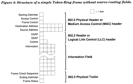
This structure can hold sufficient information to get a frame from one station to another station on the same ring. However, it has no fields to hold information about the route between stations on different rings.
In order for a frame to hold the necessary information for travel between stations on different rings, the frame must be modified. A frame with routing information is shown in Figure 5.
Figure 5: Structure of a Token-Ring frame with source-routing fields.
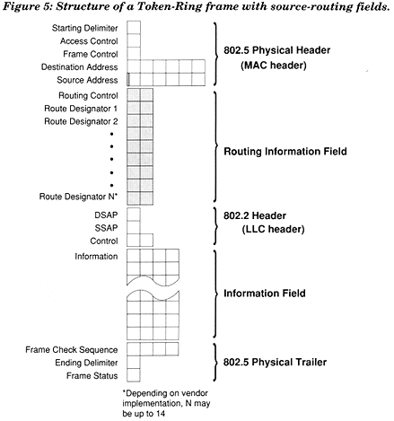
Figure 5 highlights the three most important areas of the frame for source routing: the first bit of the Source Address Field, the Routing Control Field, and the Route Designator Fields.
The Source Address Field
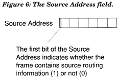
A binary 0 in the first bit of the Source Address Field would indicate that the frame contains no source routing information. Whenever a station includes routing information in a frame, it sets this bit to 1. This signals a receiving station to account for the routing information when it parses the contents of the frame. When a bridge detects a 1 in the first bit of the Source Address Field, it examines the frame's Routing Information Field to see if it should pass the frame to the bridge's adjoining ring. See Figure 6.
Figure 6: The Source Address Field.
The Routing Control Field
This field contains administrative information including the following:
The frame type (single-route broadcast, all-routes broadcast, or specifically routed)
The length of the entire Routing Information Field (the Routing Control Field plus the Route Designator Fields)
The direction the Route Designator Fields should be read by the bridge (forward or backward)
The largest size the Information Field can be as it is sent along the route
Figure 7: The Routing Control Field.
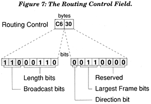
The meaning of the numbers in the field shown in Figure 7 is explained in detail later.
The Route Designator Fields
Under the IEEE definition, a frame can hold from 2 to 14 Route Designators, allowing it to traverse up to 14 rings across 13 bridges in a given direction. (It is important to note that vendor implementations differ in this sense; IBM, for example, allows 2 to 8 Route Designators, allowing frames to traverse up to 8 rings across 7 bridges in a given direction.) Because the information in the Routing Control Field gives the current length of the Routing Information Field, the number of Route Designators, the number of Route Designator Fields can vary without being parsed incorrectly by receiving stations. The Route Designator Fields in Figure 8 read "from Ring 001, across Bridge 1, to Ring 002."
Figure 8: The Route Designator Fields.
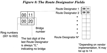
Figure 8 shows empty Route Designators only to indicate that more than two may be used; in practice, only the needed number of Route Designators are added to the frame.
Although the Source Address Field and the Routing Information Fields make source routing possible, a station on one ring must still obtain the route to t\a station on another ring before this route in called route determination.
Source-Routing Bridge Operation
One of the pillars of source routing is the source-routing bridge. An explanation of the basic function of this kind of bridge is vital to understanding route determination. Source-routing bridges come in a variety of platforms including 80286, 386, 486, and RISC machines. Although each kind may use different software, all of them have in common several functions that identify them a source-routing bridges. The basic function of a source-routing bridge is to provide a link between stations on different rings. When the bridge is started, several parameters are configured, including the bridge number, ring numbers, and the single-route broadcast selection mode.
Rules for Source-Routing Bridges
Each source-routing bridge must be assigned a hexadecimal number (0-9, A-F). This number does not have to be unique unless bridges are used in parallel (attached to the same two rings). This bridge number is contained in the bridge portion of the Route Designators (1 is the default bridge number).
During bridge configuration, each ring, or segment, connected to a source-routing bridge is assigned a unique hexadecimal number (001-FFF). All bridges connected to the same ring must be configured to use the same ring number for that ring. When the Route Designator Fields are used, this unique ring number is placed in the ring portion of each Routed Designator. The ring numbering feature of the bridge allows all stations on a ring to know the number of the ring they are connected to.
Ways to Configure a Source-Routing Bridge
A bridge can be configured manually as a single-route broadcast bridge (the default setting) or as an all-routes broadcast bridge. Or, it can be allowed to configure itself automatically to all-routes or single-route mode by negotiating with other bridges on the network.
A source-routing bridge that is set up as a single-route broadcast bridge will forward frames that are:
All routes broadcast
Single-route broadcast
Specifically routed
A source-routing bridge that is set up as an all-routes broadcast bridge will forward frames that are:
All-routes broadcast
Specifically routed
A bridge set up this way is also described as "single-route broadcast forwarding inactive" because it will not forward single-route broadcasts.
Two features of bridges prevents route determination frames from traveling endlessly around the network. The first is that a bridge will not forward a frame to its other ring if the Route Designator Fields indicate that the frame has already been on the bridge's other ring. The second feature is the Hop Count Limit, which restricts the number of bridges an all-routes broadcast frames may cross. The default setting for IBM's Token-Ring bridge is 7, and the range is 1-7. Decreasing the value of this parameter does not affect single-route broadcasts or specifically routed frames, which in this case my cross up to 7 bridges even if the Hop Count Limit on a given bridge is set to less than 7. When either an all-routes broadcast or a single-route broadcast frame has crossed 7 IBM bridges and reaches the eighth, it is discarded.
Route Determination
A ring station that requires the resources of a peer or server on a connected ring must first find a route to that station. Once a route is known, the two stations use it to exchange all frames. Ring stations may use either an all-routes or single-route broadcast frame to determine the route to another station.
Figure 9 illustrates how WS1 finds a route to FS1 using an all-routes broadcast frame. WS1 places a frame on Ring 1 that contains the node address of FS1 as its Destination Address and is labeled as an all-routes broadcast in the Routing Control Field. This frame is copied by all of the source-routing bridges onto their adjacent rings (unless the frame is marked in the Route Designator Fields as having been on the adjacent ring already).
Figure 9: WSI issues an all-routes broadcast in search of the route to FS1; FS1 receives one coopy of the broadcast for each route between WS1 and FS1."
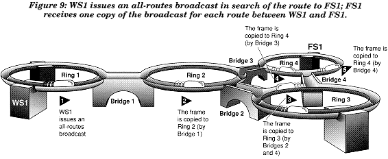
Since there are two paths to Ring 4 from Ring 1, two copies of the frame will appear on Ring 4 (two copies will also appear on Ring 3). As each bridge copies the frame onto its adjoining ring, it adds Route Designators to indicate
the ring number of the frame is copied from;
the number of the bridge passing the frame; and
the ring number the frame is copied to.
When FS1 receives the all-routes broadcast frames, it realizes that a station is trying to determine its location on the network. FS1 can respond to each of these frames either with a single-route or all-routes broadcast frame. Or, it can reverse the order of the routes that the bridges have placed in the Route Designator Fields of WS1's all-routes broadcast frames and return specifically routed frames addressed to WS1.
After receiving the response, WS1 can choose the shorter of the two routes (in this case, the route through Bridge 3) for all subsequent communication with FS1.
In contrast with this example, if WS1 were to use a single-route broadcast frame to locate FS1, only those bridges that are configured to pass single-route broadcasts will copy the frame to their adjacent rings. For example, if all of the bridges in the figure above (except Bridge 3) were configured to pass single-route broadcast frames, only one copy of the frame sent by WS1 will appear on Ring 4. (This frame would travel from Ring 1 through Bridge 1 to Ring 2, then through Bridge 2 to Ring 3, and finally through Bridge 4 to Ring 4.)
The example in the previous figure shows that FS1 can respond with several frame types. In fact, WS1 is not limited in the way it initiates the route determination to begin with. The options of the source and destination stations are listed below:
|
WS1 |
FS1 |
|
Send Options |
Return Options |
|
Single-route |
Single-route |
|
All-routes |
All-routes |
|
Include Data |
Specifically routed |
This combination of options is flexible enough to allow either the source station or the destination station to determine the best route. Which options are used in a network is an implementation issue, decided by each vendor whose software is used on the network stations (or by the user if the software is configurable).
The option for the sending station to include data in the route determination frame can conserve network bandwidth by reducing the total number of frames used in a particular communication. However, if multiple routes exist, using this option can degrade network performance because several copies of the larger frame (containing data) may circulate on the network.
A Closer Look at Route Determination
The preceding examples have shown the basics of route determination, but this is not enough for designers or administrators who may need to read network analyzer traces to examine what is happening on a network. To assist those who need this kind of information, the following example examines part of the source-routing frame at the binary level.
The Route Determination Process Begins
Figure 10 show the broadcast frame sent by WS1 during the first three stages of the route determination process.
Figure 10 The first steps of route determination.
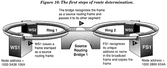
When WS1 originates the route determination frame (broadcast), it indicates in the first bit of the Source Address Field that the frame contains routing information. This signals the bridge that the frame should be examined and possibly passed on to the adjoining ring.
In the Frame's Destination Address Field, WS1 inserts the unique node address of FS1. Higher-level protocols such as NetBIOS or NetWare Core Protocol (NCP) can obtain this unique address through a search for the name "FS1" on the network.
Figure 11 shows the specific numbers place in the Routing Information Field at the three stages shown in Figure 10.
Figure 11: Number placement in the Routing Information Field.
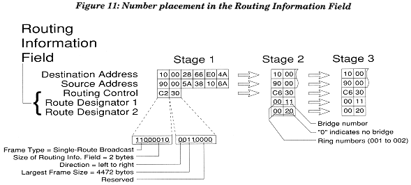
Stage 1. As WS1 issues the frame, it place the Destination and Source Addresses in the MAC header.
The first byte (C2) of the 2-byte Routing Control portion of the Routing Information Field contains the following information: the binary 110 at the beginning of the byte signifies a single-route broadcast; the remaining binary 00010 (or decimal 2) indicates that the Routing Information Field is 2 bytes long. The second byte (30) contains the following information: the binary 0 at the beginning of the byte indicates the Route Designator Fields (which don't exist yet) should be read from left to right; the next part, binary 011, designates the largest frame size (excluding headers) that WS1 can transmit, and is reduced by any bridge that cannot handle the current given size; the remaining binary 0000 is blank, reserved for future use.
The Destination Address and the Source Address remain the same through the first three stages. Note, however, that the hard-coded Source Address of the adapter in WS1 is actually 1000 5A38 106A; when WS1 changes the first bit of the Source Address set from 0 to 1 to designate a source-routing frame (before sending the frame), the equivalent hexadecimal Source Address becomes 9000 5A38 106A.
Stage 2. As the bridge prepares to pass the frame to Ring2, it modifies several parts of the Routing Information Field.
It changes the first byte of the Routing Control Field from C2 to C6. This reflects changing the last five bits to indicate a new length of 6 for the Routing Information Field, because the bridge is adding 4 bytes to the Routing Information Field (previously 2 bytes long). These 4 bytes, added in the Route Designator Fields, can be interpreted directly in their hexadecimal form: the number of the "from" ring (Ring 001), the bridge number (Bridge 1), and the number of the "to" ring (Ring 002). The final digit of the last Route Designator is always 0, to indicate no bridge.
If the frame were to traverse an additional bridge (Bridge 2), that final 0 would be changed to 2, and the third Route Designator would read 0030 (assuming a Ring 003), with the last digit again indicating no bridge.
Stage 3. FS1 receives the frame exactly as it left the bridge.
To understand how all stations on each ring have access to all frames on the ring, it is important to note that the route determination frame originated by WS1 travels completely around Ring 1 before WS1 removes it from the ring. If FS1 were on the same ring, it would copy the frame as it moved around the ring and then issue a direct response. In this example, however, as the frame is traveling around Ring 1, Bridge 1 copies it. After Bridge 1 puts this copied frame on Ring 2, the frame travels completely around Ring 2 before Bridge 1 removes it. During the time this frame travels around Ring 2, FS1 copies it and formulates a response.
The Route Determination Process Ends
FS1 responds to WS1's broadcast because its unique address is in the Destination Address Field of the frame's MAC header. The other stations (WS1 and WS3) do not send response frames back to WS1 because they do not match the Destination Address of the frame.
Figure 12: The final steps of route determination.
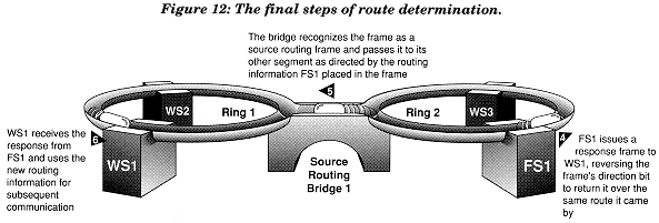
The figure below shows the specific numbers in the Routing Information Field at the three stages shown in Figure 12.
Figure 13: Specific numbers in the Routing Information Field.
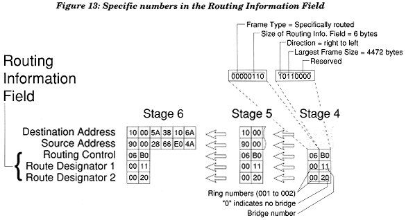
Stage 4. As FS1 issues the response frame, it includes 6 bytes in the Routing Information Field.
The first byte (06) contains the following information: the binary 000 at the beginning of the byte signifies a specifically routed frame; the remaining binary 00110 (or decimal 6) indicates that the Routing Information Field is 6 bytes long. The second byte indicates (B0) contains the following information: the binary 1 at the beginning of the byte indicates the Route designator Fields should be read backwards (this feature allows all bridges to read the same Route Designator Fields for frame travel in either direction); the next part, binary 011, designates the largest frame size (excluding headers) that can be transmitted between WS1 and FS1; the remaining binary 0000 is blank, reserved for future use.
The Destination Address now reflects the hard-coded unique adapter address of WS1 (1000 5A38 106A). The Source Address contains the unique adapter address of FS1 (1000 2866 E04A), slightly modified to 9000 2866 E04A to reflect the setting of the first bit of the Source Address Field from 0 to 1 to indicate a source-routing frame.
Stage 5. Because this frame is a specifically routed frame, the bridge does not change any of the information in the frame.
The Routing Information Field contains the routing information that directs the bridge to pass it from Ring 2 to Ring1.
Stage 6. WS1 receives the frame exactly as it let the bridge (and FS1). WS1 and FS1 will continue to use this route until the route between them is altered.
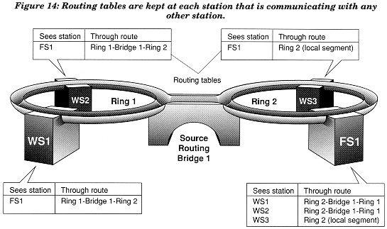
Once route determination is complete, the stations on a network each maintain a table of the routes to other stations they communicate with. Figure 14 shows how three workstations (WS1, WS2, and WS3) maintain a table of individual routes to FS1, the file server they have a current session with. Conversely, FS1 maintains a table of the routes to WS1, WS2, and WS3. The same idea applies for peer-to peer communication (for example, WS1 and WS3 would keep track of the route to the other).
Figure 14: Routing tables are kept at each station that is communicating with any other station.
As you can see from the step-by-step examples in the last few pages, a thorough understanding of the route determination process requires knowledge of the pieces of source routing information in Token-Ring frames. Now that you have a better understanding of how source routing works, we can look at a few examples of how to apply that knowledge in looking at broadcast traffic overhead, balancing the network load, and implementing parallel bridges.
Broadcast Traffic Overhead
As we have seen, the major difference between an all-routes broadcast frame and a single-route broadcast frame is in the number of frames appearing on the destination ring. An all-routes frame will appear as many times on the destination ring as there are routes to that ring. See Figure 15.
Figure 15: If WS1 issues an all-routes broadcast in search of the route to FS1, FA1 receives one copy of the broadcast for each route between WS1 and FS1.
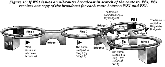
In contrast, a single-route frame will appear as many times on the destination ring as there are single-route broadcast routes to that ring. That is, if all the bridges on the network in Figure 15 were set up as single-route bridges, a single-route broadcast from WS1 would appear two times on Ring 4, just as with an all-routes broadcast. However, it only bridges 1, 2, and 3 were set up as single-route bridges, then only one copy of a single-route broadcast from WS1 would appear on Ring 4. Since the intent of having a single route over the network is to reduce traffic, creating more than one "single route" would defeat this purpose. It is important, therefore, to effectively place each bridge and know its broadcast mode.
Using single-route broadcast frames and single-route bridges can clearly reduce the amount of traffic caused by the route determination process. By placing single-route bridges strategically in the network, an administrator can create preferred routes for route determination, freeing from most broadcast traffic those rings whose operation is most sensitive to additional traffic.
Parallel Bridges and Load Balancing
As we mentioned earlier in the AppNote, source routing makes it possible to connect two or more bridges to the same two rings. This configuration, called parallel bridging, not only guards against the failure of a single bridge, but can also help balance the network load.
This section contains two examples of parallel bridging during route determination. In both examples, two bridges are used in parallel: Bridge 1 is a single-route broadcast bridge and Bridge 2 is an all-routes broadcast bridge. The first example shows how they work with a single-route broadcast; the second shows an all-routes broadcast.
Figure 16 and Figure 17 show the operation of parallel bridges during a single-route broadcast. In Figure 16, WS1 sends a single-route broadcast to locate FS1 on the network. Since only the single-route bridge fords the single-route broadcast from Ring1 to Ring2, FS1 receives just one copy of the broadcast frame.
Figure 16: A single-route broadcast over parallel bridges.
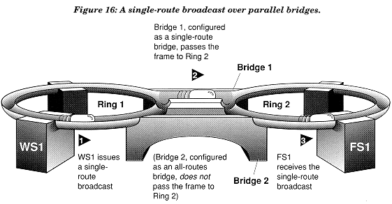
In the second part of the example, FS1 responds to the single-route broadcast with a specifically routed frame. This response ensures that WS1 is able to choose from all available routes, ultimately balancing the load between Bridge 1 and Bridge 2.
Figure 17: A response to a single-route broadcast over parallel bridges.
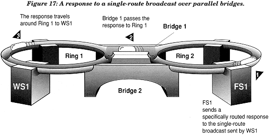
WS1 chooses the route of the first response frame that it receives from FS1. It sends subsequent frames a specifically routed frames, as specifically routed frames, containing the routing information (ring numbers and bridge numbers) to route these frames to FS1. After FS1 receives the first specifically routed frame from WS1, it also uses the route selected by WS1.
In Figure 18, WS1 sends an all-routes broadcast frame in search of FS1. The frame is copied to Ring 2 by both bridges.
Figure 18: An all-routes broadcast over parallel bridges.
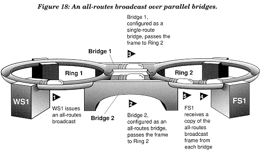
Remember that an all-routes broadcast route determination frame will appear as many times on the destination ring as there are routes to that ring. Although this increases network traffic compared to using single-route broadcast frames, all-routes broadcast frames have a unique advantage in balancing the load on the network.
Figure 19: A response to an all-routes broadcast over parallel bridges.
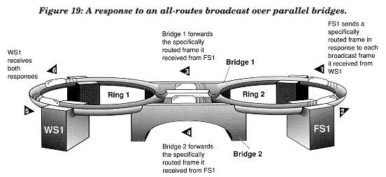
In Figure 19, WS1 and FS1 have the option of selecting which of the bridges they will use to communicate with each other. If Bridge 1 is heavily loaded with traffic when WS1 issues the all-routes frame, WS1 and FS1 can route over Bridge 2 for better performance.
Conclusion
In the AppNote we have outlined the fundamentals of source routing. In its simplest definition, source routing allows 802.5 token rings to be interconnected with source-routing bridges. Using special fields within the 802.5 packet, a node on the network can determine a route--through these source-routing bridges--to another node, and then route packets to that other node. In the route determination process, nodes can use either single-route broadcasts or all-routes broadcasts. Single-route broadcasts reduce the amount of traffic overhead caused by route determination packets and allow system administrators to create referred routes on the network. All-routes broadcasts create more traffic overhead but allow for load balancing.
Ultimately, source routing provides flexibility for systems designers and administrators to customize networks to the needs of the environment, whether the priority is performance, reliability, or ease of management.
In future AppNotes we will discuss source routing issues in greater depth, including the source-routing spanning tree protocol and NetWare's implementation of source routing.
Appendix A: Use of Terms
Individuals who work in the IBM and Novell environments have come to use a mixed set of terms to describe the logical and physical pieces of networks. Because some identical terms describe different concepts and similar concepts are sometimes described with different terms, understanding the terminology when integrating products from these two (and other) environments can be difficult.
Below is a list of terms which typically need clarification; additional terms are defined as they are used in the preceding AppNote. Unless otherwise specified in the AppNotes, the IBM term is used (frame, for example, instead of packet).
|
Term |
IBM meaning |
Novell meaning |
|
Broadcast |
To send a frame to more than one station on a ring using FFFF FFFF FFFF in the Destination Address Field (this is also called an all-stations broadcast). |
Same as an all-stations broadcast within the Token-Ring environment. Also commonly used for Service Advertising Protocol (SAP) and Routing Information Protocol (RIP) broadcasts. SAP and RIPbroadcasts are sent by NetWare routers and servers. |
|
To send a route determination frame to determine the route to another station on the network (this can be an all-routes or a single-routebroadcast). |
BROADCAST is also a NetWare command typed at the file server console to send a brief message to all users logged in to or attached to that file server or to a list of users or connection numbers. |
|
|
Ring Number |
A unique three-digit hexadecimal number (001-FFF) thatdifferentiates bridged rings on a Token-Ring network. The ring number is used at the ISO Data Link layer (Medium Access Control sublayer). In a combined Novell/other-vendor environment, both ring number and network number are used. The term "LAN segment number" is synonymous with ring number. |
Same definition as for IBM. Not the same as "network number." |
|
Network Number |
Not defined for the Token-Ring Network; should not be confused with ring number. |
Synonymous with Novell's "network address." An eight-digit hexadecimal number (1 through FFFFFFFE) that uniquely identifies a network cabling segment. The network number used by NetWare is used at a higher OSI level than the ring number. Thenetwork number is set with NETGEN (v2.1x), INSTALL (v2.2), or with the BIND IPX command (v3.x). |
|
Network Address |
Not defined for the Token-Ring Network; should notbe confused with ring number. |
Synonymous with Novell's "network address." |
|
Bridge Number |
A one-digit hexadecimal number (0-9, A-F) given to abridge in a multiple-ring network. This number is not necessarily unique on a network, but must be unique where parallel bridges are used. |
Not defined. NetWare routers (traditionally calledbridges) are not assigned an identifying number; instead, each network adapter in the bridge must use the network number, or address, of the segment to which it is attached. |
|
Router |
IBM does not define this as a specialized device in the Token-Ring network. The function of the routing in the Token-Ring environment is handled by the source and destination nodes on the network. Source-routing bridges pass frames from ring to ring, but do not actually route the frames. |
An internetwork device that keeps routing tables, answersqueries, published routing information, and routes frames to their destination through the most efficient path. The function of routing in the NetWare environment is handled by what Novell has called bridges (IEEE chose the term "router" some time after Novell began using "bridge"). New versions of NetWare refer to routers instead of bridges. This AppNote uses the term "router" to refer to what was previously called a Novell bridge, and "bridge" to refer to a source-routing bridge. |
|
Bridge |
Source-routing bridge: a packet-forwarding device that gets itsforwarding instructions from Route Designator Fields added to the MAC (Medium Access Control) header (currently used only in the Token-Ring environment). |
Same as IBM term for source-routing and transparent bridges. Novell has in the past referred to its routers as bridges. New versions of NetWare call a router a router. This AppNote uses the term "router" torefer to what was previously called a Novell bridge. and "bridge" to refer to a source-routing bridge. |
|
Transparent bridge: a packet-forwarding device that gets it forwarding instructions from the Destination Address Field in the MAC header. Transparent bridges learn about the location of nodes on a network by examining the Source Address Field of packets sent on the network. Transparent bridges are currently used in both the Token-Ring and Ethernetenvironments. End nodes need not be aware that transparent bridges exist on the network. |
||
|
Frame |
The basic element of transmission in the Token-Ring environment. |
Same definition as for IBM. "Frame" and "packet" are synonymous. In this series of AppNotes we use "frame" except where "packet" makes sense (for example, Internetwork Packet Exchange, or IPX). |
|
Packet |
Synonymous with "frame." The IBM Local Area NetworkTechnical Reference, for example, uses "packet" to describe data moving between stations (including Token-Ring, PC-Net, and Ethernet); the IBM Token-Ring Network Architecture Reference, however, uses "frame" to describe the same thing in the Token-Ring environment. |
The basic element of transmission in a NetWare network. "Packet" and "frame" are synonymous to Novell. n this series of AppNotes we use "frame" except where "packet" makes sense (for example, Internetwork Packet Exchange, or IPX). |
|
SAP |
Service Access Point. The logical point (made available by anetwork adapter) where information is received and transmitted. Similar to the "socket" used by IPX. |
Service Advertising Protocol. Every 60 seconds, severs on a NetWare network advertise their services on the network using this protocol. |
Appendix B: Token-Ring Frame Structure
This appendix provides additional information about the Token-Ring frame structure, including the Routing Information Field used for source routing.
Figure 20: Physical Header.
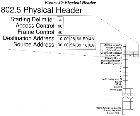
|
Field |
Purpose |
Explanation |
|
Starting Delimiter |
Synchronized the receiving adapter with the frame(or token) to follow. |
This one-byte preamble begins every frame and toke, Because it is not distinguishable as a valid byte of data, this field is unique from the other fields in the frame. The starting delimiter is only a part of the frame while it is on the wire; intelligent components in the adapter never see it. |
|
Access Control |
Holds information that controls access to the ring. |
This one-byte field is the second byte of every frame and token. It indicates the current priority of a frame (or token), distinguishes a frame from a token, prevents "homeless" tokens orframes from continuously circling the ring, and stores requests for priorities from ring stations. |
|
Frame Control |
Indicates the type of frame: Medium AccessControl (MAC) or Logical Link Control (LLC). |
The example value of hexadecimal 40 (binary 0100 0000) indicates an LLC frame. Hexadecimal 00 (binary 0000 0000) indicates a MAC frame, which all stations with a matching individual or group destination address will copy. |
|
Destination Address |
Identifies the ring stations that should copy the frame. |
This six-byte field contains a hexadecimal address, which contains one of the following: individual address (identifies a specific ring station) group address (identifies a group of destination ring station) null address (identifies a frame that can be sent, but not received except by the originating station, for the purpose of clearing the ring) all-stations broadcast address (identifies all ring stations on a given ring or interconnected rings, and is different from an all-routes broadcast, which is copied by all bridges.) The first bit of byte one of the address identifies the address as an individual address (0) or a group address (1). The second bit of byte one identifies the address as universally administered (0) or locally administered (1). The first bit of byte two of the address indicates whether an address that is locally administered is a group address (1) or a functional address (0, used for LAN management functions). |
|
Source Address |
Identifies the originating ring station. |
This six-byte field contains a unique hexadecimal address. Individual address may be assigned in one of two ways: by universal administration (IEEE guarantees uniqueness) by local administration (assigned by a local administrator; locally assigned addresses must still be unique in the Token-Ring Network where they are used) The first bit of byte one of the address is set to 1 when the frame contains a Routing Information Field; it is set to 0 when no routing information is present. By setting this bit to 0, a ring station that does not use source routing can use the same ring as source-routing stations do, but if cannot send or correctly receive frames that contain source routing information. The second bit of byte one identifies the address a universally administered (0) or locally administered (1). |
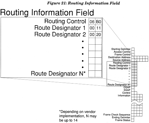
Figure 21: Routing Information Field.
|
Field |
Purpose |
Explanation |
|
Routing Control |
Indicates several things about how the frame is to traveland how other stations are to parse the rest of the information in the frame. |
This two-byte field is the first part of the Routing Information Field, which provides the vehicle for source routing. The Routing Information Field as a whole is optional when source routing is not needed. |
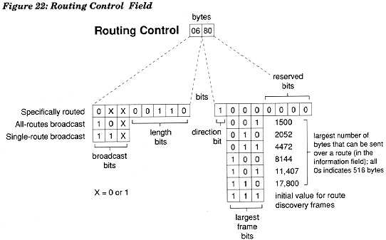
Figure 22: Routing Control Field.
|
Routing Control (Cont'd) |
The two bytes of the Routing Control Field hold four distinctivepieces of information, as shown in the figure above. They are as follows: Broadcast Indicators (indicating the broadcast type of the frame as explained below) Length Bits (indicating the binary length of the Routing Information Field, enabling stations to correctly parse the rest of the frame; in the example above,00110=6, which indicates a 6-byte field, including the Route Designators, explained below) Direction Bit (indicates whether bridges should read the Route Designators forward or backward, which allows the same Routing Information Field to be used for travel either direction between two points) Largest Frame Bits (signifies the largest frame that can pass alone a specific route between two stations) The fifth are in the Routing Control Field is reserved for future use. The first three bits (broadcast bits) of byte one indicate whether the route is: Specifically routed (the Route Designator Fields already contain a specific route for the frame to travel; the source node determines what that route is) All-routes broadcast (a frame that is to be copied to all routes on the network) Single-route broadcast (a frame that is to be copied around the network in a manner thatplaces only one copy on each ring) |
|
|
Route Designator |
Indicates the route a frame has traveled or is to travel. |
In a network with two rings joined by a single bridge, a frame passed from Ring1 to Ring 2 will contain four bytes of Route Designators, 00 11 00 10, which is read "from Ring 001, across bridge 1, to Ring 002." If there were another bridge (Bridge 2) to pass the frame to another ring (Ring 003), the Route Designator Fields 1, 2, and 3 would read 0011, 0022 and 0030, respectively. The final digit of the last Route Designator is always 0, to indicate no bridge. Bridges examine the Route Designators in every source-routing frame to determine whether the frame has already been on the bridge's other ring (via another route). If the other ring number is in a Route Designator, the bridge doesn't pass the frame on. The frame may contain up to fourteen Route Designators (IEEE definition) or up to eight Route Designators (IBM definition). This limits the size of the network to fourteen rings/thirteen bridges (IEEE) or eight rings/seven bridges (IBM) in any one direction. |
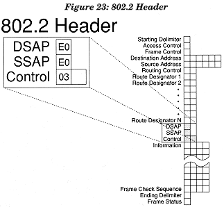
Figure 23: 802.2 Header.
|
Field |
Purpose |
Explanation |
|
DSAP |
Identifies the Destination Service Access Point the frame is sent to. |
In the example above, E0 identifies NetWare as the DSAP. The DSAP is similar to a NetWare socket, which identifies a particular process within a station. The DSAP, SSAP, and Control fields constitute the Logical Link Control (LLC) portion of the frame. This AppNotedoes not deal with LLC in detail. For more information, refer to IEEE documents or the IBM Token-Ring Network; Architecture Reference, listed in the bibliography. |
|
SSAP |
Identifies the Source Service Access Point the frame issent from. |
In the example above, E0 identifies NetWare as the SSAP. The SSAP is similar to a NetWare socket, which identifies a particular process in the station which originates a frame. |
|
Control |
Holds commands, responses, sequence numbers, and otherinformation. |
In the example above, 03 identifies the frame as an unnumbered information (UI) frame, commonly known as a datagram frame. |
Novell currently uses 03 as its default control type for source-routing frames. When a sequenced-type of frame is identified in the first byte, the second byte (which is otherwise optional) gives the frame's sequence number. Other control types are possible, but will not be covered here.
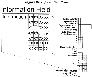
Figure 24: Information Field.
|
Field |
Purpose |
Explanation |
|
Information |
Holds higher-level protocol information or actualdata such as part of a file to be stored. |
This field is variable in length. It holds information from protocols such as NetBIOS or IPX, layered around user data that is being sent in the frame. The Information Field provides a vehicle for network management protocols or other third-partyprotocols to travel across the network between the headers and trailers in the frame. |
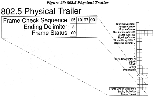
Figure 25: 802.5 Physical Trailer.
|
Field |
Purpose |
Explanation |
|
Frame Check Sequence |
Provides a 4-byte cyclical redundancy checkfor parts of the frame. |
The CRC covers everything from the Frame Control field through the Frame Check Sequence itself, inclusive. |
|
Ending Delimiter |
Identifies the end of the frame. |
This one-byte delimiter ends every frame and token. Because it is not distinguishable as a valid byte of data,this field is unique from the other fields in the frame. The ending delimiter is only a part of the frame while it is on the wire; intelligent components in the adapter never see it. |
|
Frame Status |
Provides status information to the source stationabout how the frame was received. |
The information contained in this one-byte postscriptallows the source station to know if the destination station (1) copied the frame; (2) is inactive or does not exist; or (3) exists but did not copy the frame. |
Appendix C: Bibliography
Administering Token-Ring networks with source routing is a task that requires a thorough understanding of the subject. We recommend the following reference library as an information tool to assist you in designing, implementing, and administering Token-Ring networks.
Books*
IBM Token-Ring Architecture Reference, pp. 2-5 through 3-10. IBM part number SC30-3374-02.
IBM Local Area Network Technical Reference. IBM part number SC30-3383.
Bridge Program User's Guide (this guide accompanies the IBM Token-Ring Network Bridge Program, Version 2.1). IBM part number 16F0493.
IBM Cabling System Planning and Installation Guide. IBM part number GA27-3677.
IBM Local Area Network Administrator's Guide. IBM part number GA27-3748.
IBM Token-Ring Network Introduction and Planning Guide. IBM part number GA27-3677.
Article
Taylor, Wayne, and Belisle, Stephen. "Token-Ring Source Routing Made Easy." NetWare Technical Journal, July 1990, pp. 64-76.
*Available from an IBM Representative or IBM Branch Office
Editor's Note: The authors accept written feedback at FAX (801) 429-5511.
* Originally published in Novell AppNotes
Disclaimer
The origin of this information may be internal or external to Novell. While Novell makes all reasonable efforts to verify this information, Novell does not make explicit or implied claims to its validity.